– 7 –
ENGLISH
WARNING :
1. Turn OFF the power before starting the work so as to prevent accidents caused by abrupt start of the sewing machine.
2. Do not perform switch operations other than those described in the following explanations.
3. Be sure to re-turn the power switch ON after one second or more has passed. If the power is turned ON immediately after turning it OFF, the sewing
machine may not work normally. In this case, turn ON the power again.
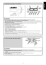
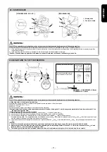
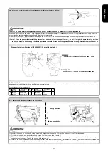
(1) Stop position after thread trimming
1) The standard needle stop position is obtained by aligning marker dot
A
on the pulley cover with white marker dot
B
on the handwheel
* For the details, refer to the Instruction Manual for the control box together.
(2) Adjusting procedure of the needle up/down stop position
* When the panel other than CP-18 is used, refer to the explanation of each panel.
1) Turn OFF the power to the machine.
2) Turn the power ON while pushing the switch
5
on the operation panel.
3) The screen display
E
indicates the setting No. 96 and
F
indicates the number of revolution.
(When the screen display is not changed, operate again steps 1) and 2).
4) Update the setting No. by switch
1
or switch
2
.
Setting No. 121 : Needle UP stop position
Setting No. 122 : Needle DOWN stop position
5) Specify the setting contents
F
within the range of -15 to 15 with switch
3
or switch
4
.
(Standard is "0". The numeric of set value indicates the approximate rotating angle. (When the numeric is set to the "+" direction, the needle UP stop
position is lowered. (Direction
C
)
When the numeric is set to "–" direction, the needle UP stop position is raised. (Direction
D
)
6) After completion of the setting, press switch
1
or switch
2
to determine the updated value. (When turning OFF the power to the machine before
performing this work, the contents are not updated.)
7) After completion of the operation, turn OFF the power to the machine. The normal operation can be performed by turning ON the power to the machine again.
15. ADJUSTING THE NEEDLE STOP POSITION
B
A
C
D
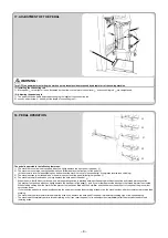
16. PEDAL PRESSURE AND PEDAL STROKE
WARNING :
Turn OFF the power before starting the work so as to prevent accidents caused by abrupt start of the sewing machine.
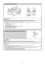
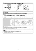
(1) Adjusting the pressure required to depress the front part of the pedal
1) When the pedal pressure spring
1
is hooked to the lower side, the pedal pressure will decrease, and when hooked to the upper side, the pedal pressure
will increase.
(2) Adjusting the pressure required to depress the back part of the pedal
1) The pressure increases as you turn reverse depressing regulator screw
2
in, and decreases as you turn the screw out.
(3) Adjusting the pedal stroke
1) The pedal stroke decreases when you insert connecting rod
3
into the left hole
4
.
3
2
1
E
F
5
4
3
1
4
2
Lower side
Upper side
Summary of Contents for DDL-9000B
Page 2: ......
Page 3: ...ENGLISH ENGLISH ...
Page 4: ......
Page 11: ...vii ENGLISH ...
Page 27: ...OTHER LANGUAGE 日本語 中文 DEUTSCH FRANÇAIS ESPAÑOL ITALIANO TÜRKÇE РУССКИЙ OTHER LANGUAGE ...
Page 130: ... 53 ...
Page 131: ......


