Page 17/19
Original issue
Jun. 2012
Service Manual
HZL-12Z
Model
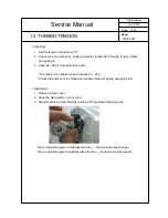
12. THREAD TENSION
〔
Checking
〕
1.
Set the length control dial at “5”.
2.
Check tension number by putting polyester thread #60 through tension plates
and pulling it.
3.
Keep 22 - 28 g at the tension of a dial.
*The tension of a bobbin case should be 22 - 28 g.
*Check the balance of top thread and bobbin thread at zigzag sewing for test.
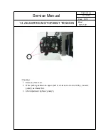
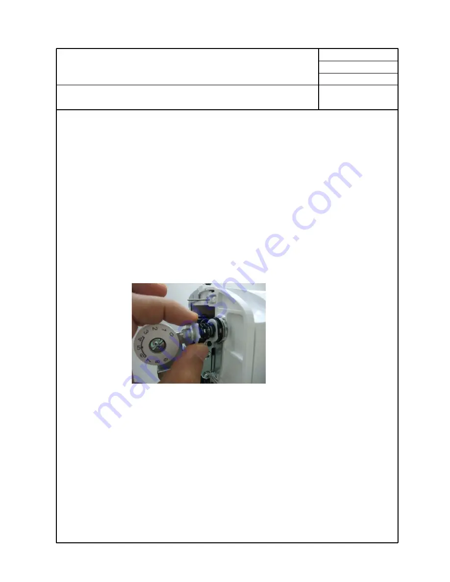
〔
Adjustment
〕
1. Remove a face cover.
2.
Keep the dial position in your mind.
3. Adjust tension as prescribed by turning a DT pressure adjusting gnat.
Turn an adjusting gnat in clockwise direction → Tension becomes stronger
Turn an adjusting gnat in anticlockwise direction → Tension becomes weaker