– 103 –
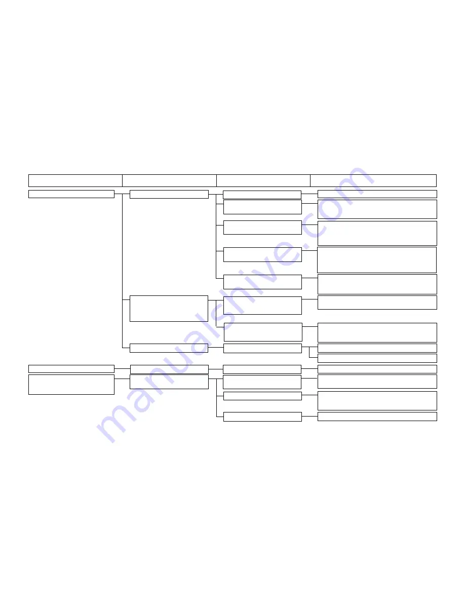
1. No display at the operation panel
1-1) No supply of DC power.
1-A) AC power is not supplied.
Examine if a power supply is available at the power switch.
1-B) The FLT board has no power
Check whether an AC voltage is available between
supply.
Pins 4-5 of CN1 in the FLT board. If no voltage is found,
check the connections around the power switch.
1-C) The SDC board has no power
Check whether DC 280V is available between
supply.
Pins 1-3 of CN17 in the SDC board. If no voltage is
found, check the connections toward the FLT board.
If there is no problem in connections, replace the FLT board.
1-D) The MAIN board has no power
Check whether DC 5V is available between Pins4-8
supply.
of CN31 in the MAIN board. Check the power supply
for the SDC board unit and examine if there is short-
circuiting in the 5V power system.
1-E) The operation panel has no
Confirm that the cable from the operation panel is
power supply.
connected to CN34 of the MAIN board. If there is no
problem in connections, replace the MAIN or PANEL board.
1-2) Detection of a momentary
2-A) There is no connection between
Check the connection between CN3 of the FLT
interruption in the SDC board
CN3 of the FLT board and
board and CN13 of the SDC board.
Led 3 on SDC board:
CN13 of the SDC board.
Flashing 9 times
2-B) No AC voltage is available
When a sewing machine for 3-phase specifications is
between Pins 4-5 of CN1 in
used in a 1-phase system, connect the power supply
the FLT board.
to red and white of the power cord led from the box.
1-3) Difference in source voltage
3-A) High input voltage
Check the 100/200V selector cord in the FLT board.
Check the source voltage.
2. Key malfunction on the operation panel
2-1) No signal transmission
1-A) Input circuit is out of order.
Replace the PANEL board.
3. Error E007
3-1) The main shaft motor of the
1-A) The motor connector is
Check CN16 of the SDC board to see if there is any
Machine lock error
sewing machine cannot rotate.
disconnected or broken.
disconnection.
LED3 on SDC board: Flashing once
1-B) The mechanism is locked.
Check the mechanism and look for the section that
is particularly overloaded or whether screws are
loose.
1-C) The driver circuit is out of order.
Replace the SDC board.
Trouble
Cause (1)
Cause (2)
Check and corrective measures
(3) Troubles and corrective measures (Electrical components) (Refer to “Block diagram A”)
Summary of Contents for LK-1900A
Page 20: ... 16 10 Hook adjustment Standard Adjustment 0mm 0mm 7 5mm 0 05 0 1mm For DPX5 For DPX17 ...
Page 90: ... 86 Grease Grease Grease Grease Grease 8 Needle thread clamp mechanism area ...
Page 91: ... 87 Grease Grease A Grease Grease Grease Grease 9 LK 1901A relations ...
Page 92: ... 88 10 LK 1903A relations Grease Grease ...
Page 114: ... 111 12 Circuit diagrams 1 Block diagram A ...
Page 115: ... 112 2 Power supply circuit diagram A ...
Page 116: ... 113 3 Power supply circuit diagram B ...
Page 117: ... 114 4 Power supply circuit diagram C ...
Page 118: ... 115 5 Servo motor circuit diagram ...
Page 119: ... 116 6 Sensor pedal VR circuit diagram ...
Page 120: ... 117 7 MAIN PANEL board circuit diagram ...
Page 121: ... 118 8 Motor solenoid circuit diagram Thread trimmer Lifting the work clamp foot motor ...


