– 104 –
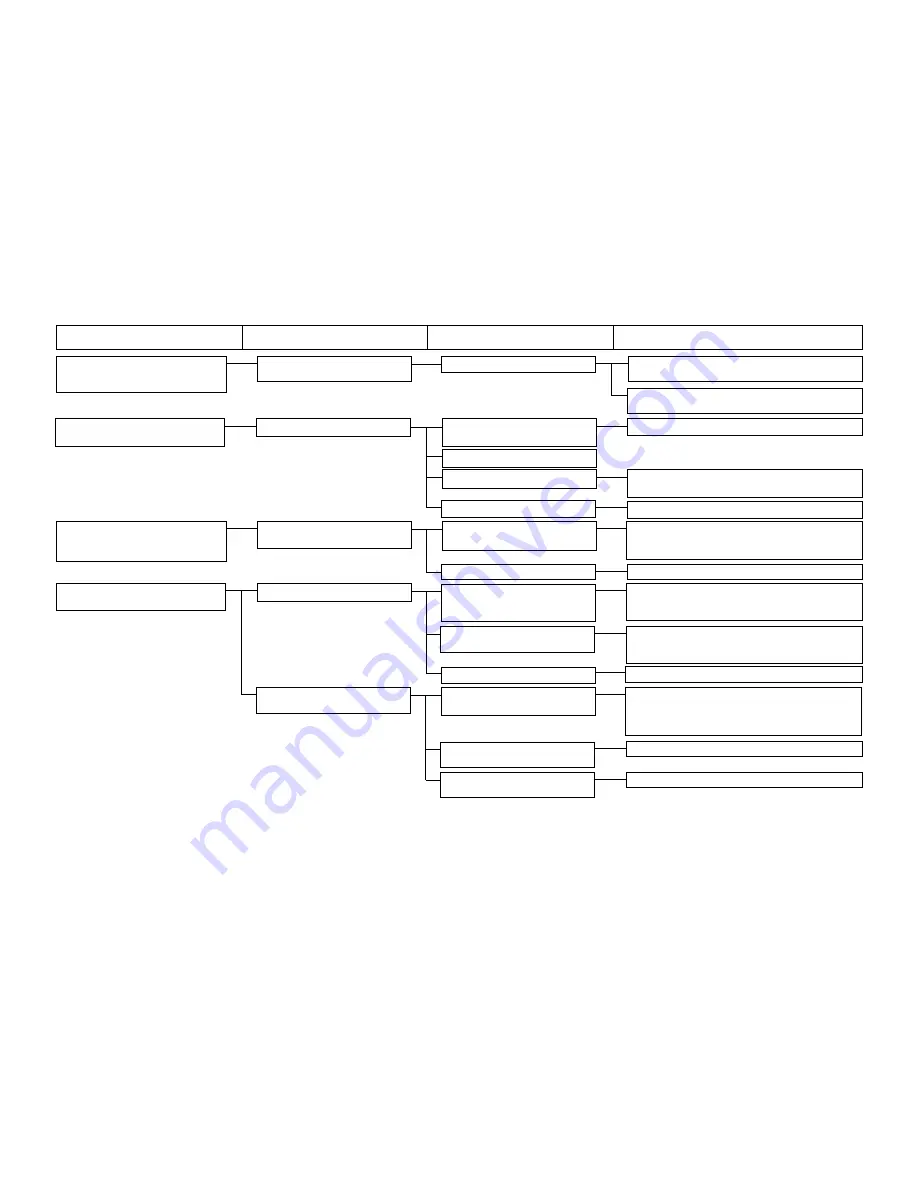
4. Error E030
4-1) Displacement of the up
1-A) The stop position is inadequate.
Try to turn the main shaft by hand. Check if there is
Needle bar up position
position
any particular heavy load.
displacement
Disconnect CN16 and check the resistance value
among pins. Replace the motor, as required.
5. Error E302
5-1) Detector switch contact open
1-A) Connector CN67 of the INT
Check CN67 of the INT board.
Head tilt error
board is disconnected.
1-B) The switch cord is broken.
1-C) The safety switch is broken.
Check whether the terminal leads are broken or the
switch turns ON/OFF correctly.
1-D) The switch does not function.
Confirm the mounting condition of the switch.
6. Error E303
6-1) Phase Z signal (main shaft
1-A) The encoder cord is broken
Confirm whether each signal is delivered to CN14 of
Main shaft motor Phase Z sensor error
motor) does not enter.
or out of order.
the SDC board. In the case of encoder error, replace
LED3 on SDC board: Flashing twice
the motor as a whole. [See the Servo Motor Circuit Diagram.]
1-B) The detector circuit is out of order.
Replace the SDC board.
7. Error E305
7-1) Irregular motor revolutions
1-A) There are irregularities in the
Check the presser bar and thread trimmer mechanisms
Thread trimmer sensor error
mechanism, such as over-
and look for the section that is particularly overloaded
loading, etc.
or whether screws are loose.
1-B) Motor leads are broken.
Disconnect CN44 (red) of the MAIN board and
The motor is out of order.
check the motor resistance. [See the Pulse Motor/
Solenoid Circuit Diagram.] Replace the motor.
1-C) The driver circuit is out of order.
Replace the MAIN board.
7-2) No sensor signal entry
2-A) The sensor is out of order or
Check whether the sensor lamp is turned ON/OFF
Use of Test Mode CP-1 or CP-2
broken.
when a metallic plate is moved closer to or separated from
the sensor plane. In the case of no lamp ON/OFF, the
sensor is broken or the connector block is disconnected.
2-B) The INT board connector is
Check the connection of CN66 (red) of the INT board.
disconnected.
2-C) Sensor mounting position is
Check and correct the sensor mounting position.
inadequate.
Trouble
Cause (1)
Cause (2)
Check and corrective measures
Summary of Contents for LK-1900A
Page 20: ... 16 10 Hook adjustment Standard Adjustment 0mm 0mm 7 5mm 0 05 0 1mm For DPX5 For DPX17 ...
Page 90: ... 86 Grease Grease Grease Grease Grease 8 Needle thread clamp mechanism area ...
Page 91: ... 87 Grease Grease A Grease Grease Grease Grease 9 LK 1901A relations ...
Page 92: ... 88 10 LK 1903A relations Grease Grease ...
Page 114: ... 111 12 Circuit diagrams 1 Block diagram A ...
Page 115: ... 112 2 Power supply circuit diagram A ...
Page 116: ... 113 3 Power supply circuit diagram B ...
Page 117: ... 114 4 Power supply circuit diagram C ...
Page 118: ... 115 5 Servo motor circuit diagram ...
Page 119: ... 116 6 Sensor pedal VR circuit diagram ...
Page 120: ... 117 7 MAIN PANEL board circuit diagram ...
Page 121: ... 118 8 Motor solenoid circuit diagram Thread trimmer Lifting the work clamp foot motor ...


