– 28 –
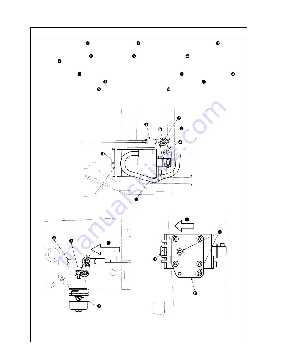
(20) AT unit connection / disconnection
Procedures of disassembling /assembling
1. Remove the set screw
of the AT link unit (front)
and take out the second thread tension
. ((19) Refer
to “Second thread tension connection / disconnection.”)
2. Draw out the cotter pin
from the pin block
of the AT link unit (rear)
. Be careful not to drop the
washer
at that time.
* Work becomes easier if the main shaft motor is removed.
3. Lift the joint block
of the AT unit upwards and take it off the pin block
of the AT link unit (rear)
.
4. Draw out the AT link unit (front)
from the plane side (in the direction of the arrow
E
) and remove it.
5. Remove the two set screws
and take out the AT solenoid unit
.
6. For reassembly, follow the steps of 5. to 1. above.
E
F
Close contact
Solenoid side
Summary of Contents for LK-1900A
Page 20: ... 16 10 Hook adjustment Standard Adjustment 0mm 0mm 7 5mm 0 05 0 1mm For DPX5 For DPX17 ...
Page 90: ... 86 Grease Grease Grease Grease Grease 8 Needle thread clamp mechanism area ...
Page 91: ... 87 Grease Grease A Grease Grease Grease Grease 9 LK 1901A relations ...
Page 92: ... 88 10 LK 1903A relations Grease Grease ...
Page 114: ... 111 12 Circuit diagrams 1 Block diagram A ...
Page 115: ... 112 2 Power supply circuit diagram A ...
Page 116: ... 113 3 Power supply circuit diagram B ...
Page 117: ... 114 4 Power supply circuit diagram C ...
Page 118: ... 115 5 Servo motor circuit diagram ...
Page 119: ... 116 6 Sensor pedal VR circuit diagram ...
Page 120: ... 117 7 MAIN PANEL board circuit diagram ...
Page 121: ... 118 8 Motor solenoid circuit diagram Thread trimmer Lifting the work clamp foot motor ...


