– 57 –
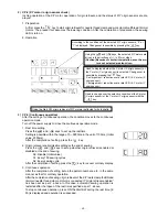
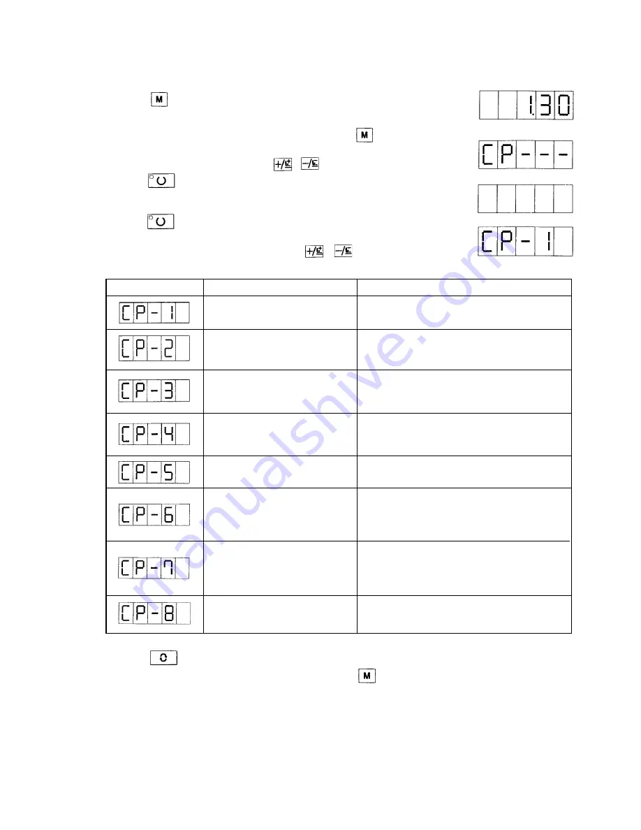
6. Press the key and define the test program number.
7. For each program, the test program can be closed when the key is pressed.
The condition of 5. recovered.
However, the continuous operation mode cannot be canceled if it is once as-
sumed. To close this mode, it is necessary to turn off the power supply.
6. Test mode
When the test mode is started, it is possible to carry out maintenance and inspection.
(1) Test mode start
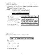
1. When the key is continuously pressed for 3 seconds in the state that the
sewing LED is turn off, the buzzer sounds and test mode start can be selected,
with the user level setting mode of the memory switch kept effective.
(Caution) The test mode cannot be selected unless the key is pressed
for more than 3 seconds.
2. Change the memory switch No. with the , keys to select the test mode.
3. Press the key. The selected test mode is assumed and a display output
test can be started. In regard to the contents of the display output test, refer to
(2) Display output test.
4. Press the key. The display output test is finished and operation moves to
the selection of another test feature.
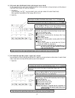
5. Select the test program No. by the use of the , keys.
Test program No.
Test program
Descriptions
Input signal check
The conditions of switches and sensor inputs
are displayed at the LED.
XY motor / origin sensor check
Inching operation of the X/Y motor, operation
of origin retrieval, and the status of X/Y origin
sensors are displayed.
Continuous operation
After the setting of continuous operational con-
ditions, the continuous operation mode is as-
sumed.
Main motor rpm check
The sewing machine is started based on the
preset rpm, and the measured rpm number is
displayed.
Output check
Output is maintained for the LK1901A material
drawing magnet.
Presser foot and thread trimmer
Inching operation of the presser foot and thread
motor and origin sensor check
trimmer motor, operation of origin retrieval,
and the status of presser origin and presser sen-
sors are displayed.
Needle thread clamp motor and
Inching operation of the needle thread clamp motor,
origin sensor check
operation of origin retrieval, and the status of
needle thread clamp origin and needle thread
clamp sensors are displayed.
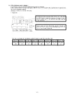
Software version display
The software versions of the MAIN and SDC
boards are displayed.
Summary of Contents for LK-1900A
Page 20: ... 16 10 Hook adjustment Standard Adjustment 0mm 0mm 7 5mm 0 05 0 1mm For DPX5 For DPX17 ...
Page 90: ... 86 Grease Grease Grease Grease Grease 8 Needle thread clamp mechanism area ...
Page 91: ... 87 Grease Grease A Grease Grease Grease Grease 9 LK 1901A relations ...
Page 92: ... 88 10 LK 1903A relations Grease Grease ...
Page 114: ... 111 12 Circuit diagrams 1 Block diagram A ...
Page 115: ... 112 2 Power supply circuit diagram A ...
Page 116: ... 113 3 Power supply circuit diagram B ...
Page 117: ... 114 4 Power supply circuit diagram C ...
Page 118: ... 115 5 Servo motor circuit diagram ...
Page 119: ... 116 6 Sensor pedal VR circuit diagram ...
Page 120: ... 117 7 MAIN PANEL board circuit diagram ...
Page 121: ... 118 8 Motor solenoid circuit diagram Thread trimmer Lifting the work clamp foot motor ...


