– 3 –
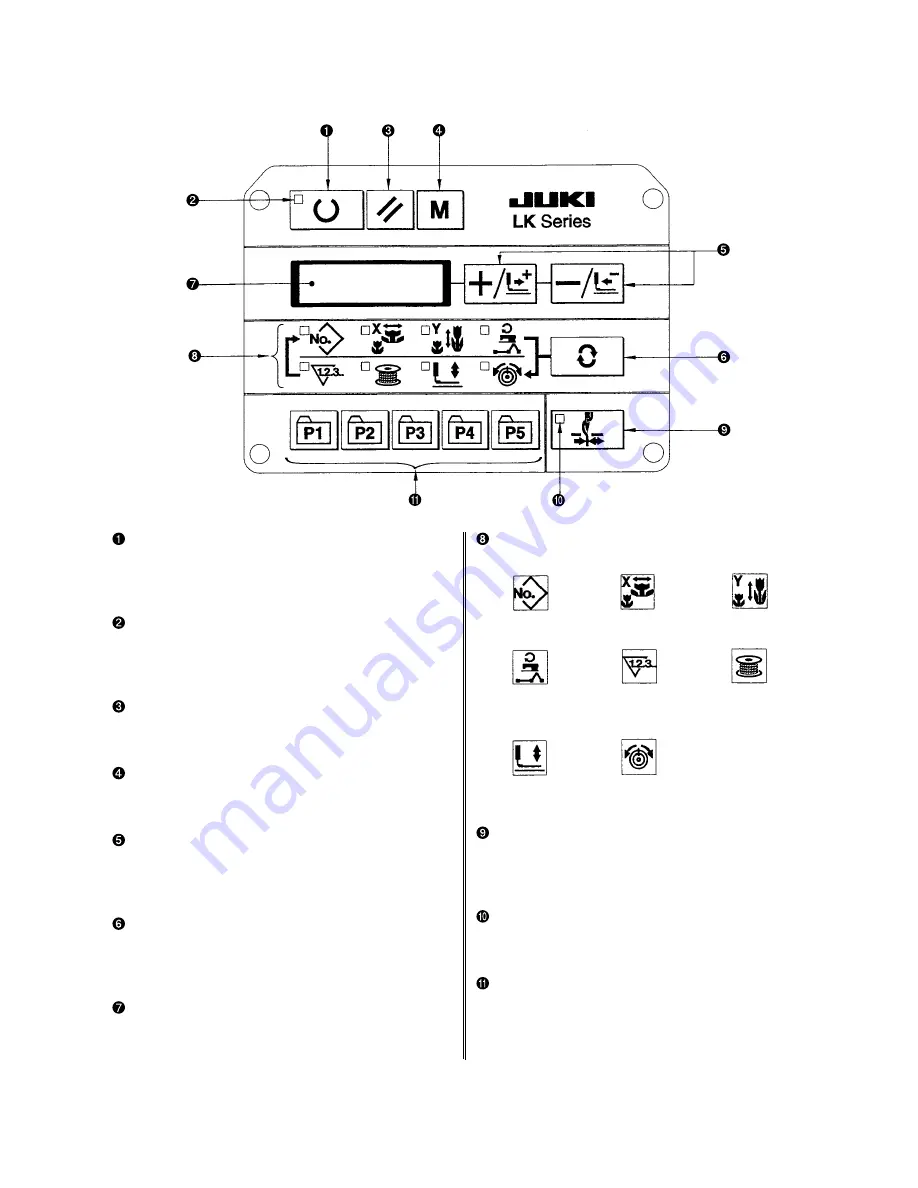
Item selection LED
LEDs of the selected items light up.
Needle thread clamp ON/OFF key
This key selects effective/ineffective of needle thread
clamp. When it is effective, needle thread clamp
disply LED lights up. (Note) 1.
Needle thread clamp display LED
When this LED lights up, needle threas clamp
operaters.
Pattern registration key
This key registers the pattern. When this key is
pressed, the pattern registered here can sew imme-
diately.
X/Y scale, sewing position, ets. can be changed and
registered.
Pattern No.
X scale
Y scale
Max. speed
Sewing counter
Bobbin winder
limitation
Work clamp foot
Thread tension
lowering
(2) Names and explanation of switches on the operation panel
“Ready” key
This key changes over the setting state from the panel
to the sewing state where the sewing machine actu-
ally operates.
Sewing LED
This LED goes off at the time of setting state and
lights up at the time of sewing state. Changeover
can be performed with “Ready” key.
“Reset” key
This key is used for canceling error or returning the
set value to the initial value.
“Mode” key
This key makes the setting mode of the memory
switch.
“+ / Feed forward” key, and “- / Feed backward”
key
This key is used for changing pattern No. and X/Y
scale, and feed forward/feed backward.
“Selection” key
This key selects the item to be set. Item selection
LED of the selected item and the set value are dis-
played.
Data indication LED
This LED indicates the set values of the selected
items such as pattern No., X/Y scale, etc.
(Note) 1. LK-1903A is set to needle thread clamp prohibited (no motion) with memory switch No. 35 at the
time of standard delivery.
Summary of Contents for LK-1900A
Page 20: ... 16 10 Hook adjustment Standard Adjustment 0mm 0mm 7 5mm 0 05 0 1mm For DPX5 For DPX17 ...
Page 90: ... 86 Grease Grease Grease Grease Grease 8 Needle thread clamp mechanism area ...
Page 91: ... 87 Grease Grease A Grease Grease Grease Grease 9 LK 1901A relations ...
Page 92: ... 88 10 LK 1903A relations Grease Grease ...
Page 114: ... 111 12 Circuit diagrams 1 Block diagram A ...
Page 115: ... 112 2 Power supply circuit diagram A ...
Page 116: ... 113 3 Power supply circuit diagram B ...
Page 117: ... 114 4 Power supply circuit diagram C ...
Page 118: ... 115 5 Servo motor circuit diagram ...
Page 119: ... 116 6 Sensor pedal VR circuit diagram ...
Page 120: ... 117 7 MAIN PANEL board circuit diagram ...
Page 121: ... 118 8 Motor solenoid circuit diagram Thread trimmer Lifting the work clamp foot motor ...


