– 66 –
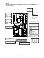
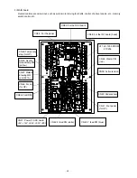
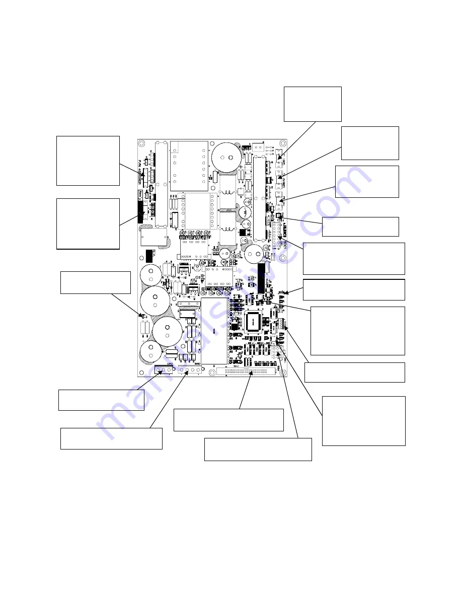
3) SDC board
The power supply is generated and error check is carried out. Main shaft control is effected, receiving the com-
mands from the MAIN board.
LED4: For power
supply check
LED3: For operation and
error check
CN10: 24V for the fan
F1: 5A
Time lag fuse
For +85V
F2: 3.15A
Time lag fuse
For +33V
F3: 2A
Quick-action fuse
For +24V
F4: 4A
Fuse fixed to the
board
For +85V source
primary
F5: 4A
Fuse fixed to the
board
For +33V source
primary
CN11: Power connector
→
MAIN board
+5V, +12V, +24V, +33V, +85V
DIPSW
2-1: For writing-off
2-2: For mode setting-off
2-3: For mode setting-off
2-4: For mode setting-off
DIPSW
1-1: For testing-off
1-2: For testing-off
1-3: For testing-off
1-4: Penetration force-off
CN17: For power supply
←
FLT board
CN16: For Main shaft motor
power
→
Main shaft motor
CN15: For MAIN communication
→
Main board
CN14: For Main shaft encoder
→
Main shaft motor
CN13: For momentary interruption
detection
←
FLT board
Summary of Contents for LK-1900A
Page 20: ... 16 10 Hook adjustment Standard Adjustment 0mm 0mm 7 5mm 0 05 0 1mm For DPX5 For DPX17 ...
Page 90: ... 86 Grease Grease Grease Grease Grease 8 Needle thread clamp mechanism area ...
Page 91: ... 87 Grease Grease A Grease Grease Grease Grease 9 LK 1901A relations ...
Page 92: ... 88 10 LK 1903A relations Grease Grease ...
Page 114: ... 111 12 Circuit diagrams 1 Block diagram A ...
Page 115: ... 112 2 Power supply circuit diagram A ...
Page 116: ... 113 3 Power supply circuit diagram B ...
Page 117: ... 114 4 Power supply circuit diagram C ...
Page 118: ... 115 5 Servo motor circuit diagram ...
Page 119: ... 116 6 Sensor pedal VR circuit diagram ...
Page 120: ... 117 7 MAIN PANEL board circuit diagram ...
Page 121: ... 118 8 Motor solenoid circuit diagram Thread trimmer Lifting the work clamp foot motor ...


