– 75 –
8. Optional features
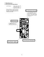
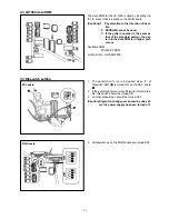
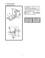
(1) Connection of PK-57
1. Connect PK-57 change cable
with CN41 of MAIN
circuit board
.
2. Connect the cord of PK-57
with the PK-57 change
cable at the rear face of the control box.
Then clamp two places with adhesive clamp
.
In addition, tighten with a screw the PK-57 ground
cable as illustrated in the figure.
PK-57 change cable
: Part No. M90135900A0
PK-57
: Part No. GPK570010B0
Adhesive clamp
: Part No. E9607603000
3. Set the memory switches as follows.
Memory Switch No.
Set value
19
2
20
1
24
1
Ground
cable
Summary of Contents for LK-1900A
Page 20: ... 16 10 Hook adjustment Standard Adjustment 0mm 0mm 7 5mm 0 05 0 1mm For DPX5 For DPX17 ...
Page 90: ... 86 Grease Grease Grease Grease Grease 8 Needle thread clamp mechanism area ...
Page 91: ... 87 Grease Grease A Grease Grease Grease Grease 9 LK 1901A relations ...
Page 92: ... 88 10 LK 1903A relations Grease Grease ...
Page 114: ... 111 12 Circuit diagrams 1 Block diagram A ...
Page 115: ... 112 2 Power supply circuit diagram A ...
Page 116: ... 113 3 Power supply circuit diagram B ...
Page 117: ... 114 4 Power supply circuit diagram C ...
Page 118: ... 115 5 Servo motor circuit diagram ...
Page 119: ... 116 6 Sensor pedal VR circuit diagram ...
Page 120: ... 117 7 MAIN PANEL board circuit diagram ...
Page 121: ... 118 8 Motor solenoid circuit diagram Thread trimmer Lifting the work clamp foot motor ...

