– 79 –
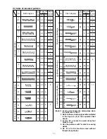
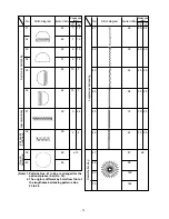
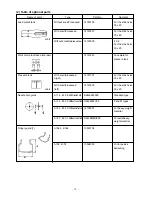
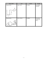
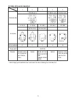
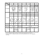
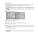
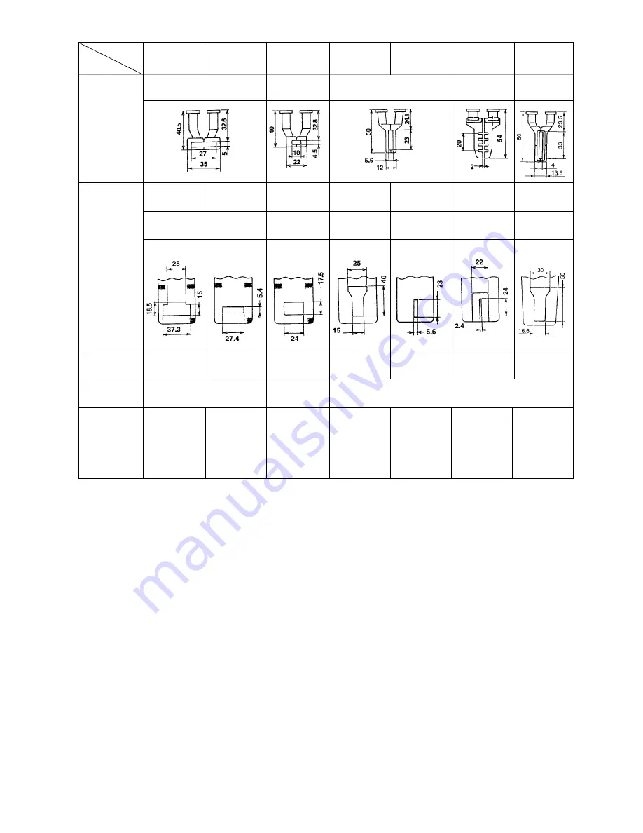
* Install a finger guard suitable for each work clamp foot when replacing the work clamp foot.
* The presser bar No. 12 (optional) should be used for the standard patterns Nos. 41 to 46 (lengthwise
bartacking).
6
7
8
9
10
11
12*
13548151 (asm.)
13542451 (asm.) 13571955 (asm.)
13561360 (asm.)
Work clamp foot
13548003
13554803
14116602
14116503
14116909
14116701
14137707
( Without knurl) ( Without knurl) ( Without knurl) ( Without knurl)
Feed plate
Sewing specification
S
H
S
F
F
F
F
* Finger guard
13548300
13533104
14135305
Remarks
Optional
Optional
Optional
Optional
Optional
14137509 (Right)
14137608 (Left)
Standard acces-
sory for H (heavy-
weight material)
type machine
head.
Standard acces-
sory for F (founda-
tion) type machine
head.
No. of the work
clamp foot
Summary of Contents for LK-1900A
Page 20: ... 16 10 Hook adjustment Standard Adjustment 0mm 0mm 7 5mm 0 05 0 1mm For DPX5 For DPX17 ...
Page 90: ... 86 Grease Grease Grease Grease Grease 8 Needle thread clamp mechanism area ...
Page 91: ... 87 Grease Grease A Grease Grease Grease Grease 9 LK 1901A relations ...
Page 92: ... 88 10 LK 1903A relations Grease Grease ...
Page 114: ... 111 12 Circuit diagrams 1 Block diagram A ...
Page 115: ... 112 2 Power supply circuit diagram A ...
Page 116: ... 113 3 Power supply circuit diagram B ...
Page 117: ... 114 4 Power supply circuit diagram C ...
Page 118: ... 115 5 Servo motor circuit diagram ...
Page 119: ... 116 6 Sensor pedal VR circuit diagram ...
Page 120: ... 117 7 MAIN PANEL board circuit diagram ...
Page 121: ... 118 8 Motor solenoid circuit diagram Thread trimmer Lifting the work clamp foot motor ...

