– 159 –
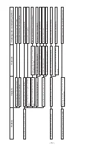
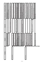
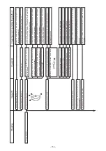
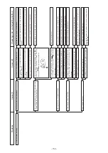
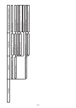
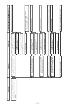
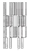
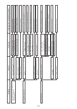
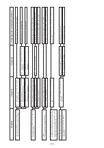
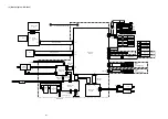
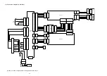
(3) Electrical parts (Also, refer to Block diagram.)
Securely connect the connector.
Replace the blown fuse after removing the cause. (10 A)
Securely connect the connector.
Replace the blown fuse after removing the cause. (10 A)
Securely connect the connector.
Check or replace the connector.
Operate or replace the MAIN circuit board.
Execute the input check mode to identify the defective switch,
and replace the (membrane switch) switch or operation circuit
board. ( ) : for LK-1930 only
Replace the operation circuit board.
1-A)
Disconnected J30 connector
1-B)
Fuse F1, F2 has blown.
2-A)
Disconnected J37 connector
POWER circuit board
2-B)
Disconnected J10 connector (MAIN circuit
board)
(J10 for LK-1930, J16 for LK-1910/20)
2-C)
Fuse F3 has blown.
3-A)
Disconnected J14 connector
(MAIN circuit board)
(J14 for LK-1930, J23 for LK-1910/20)
2-A)
Disconnected J14 connector
(MAIN circuit board)
2-B)
Failure with MAIN circuit board
1-1)
The power is not supplied to POWER circuit
board.
1-2)
Voltage of + 5 is not supplied to MAIN circuit
board.
1-3)
Operation panel
←→
MAIN circuit board has
not been connected.
2-1)
Operation panel
←→
Connection failure of
MAIN circuit board
3-1)
Failure with the switch
3-2)
Failure with the circuit board
1.
The display fails to light.
2.
Connection error of operation panel occurs.
(For LK-1930 only)
3.
Key of operation panel fails to work.
Troubles
Cause (1)
Cause (2)
Checking order and adjusting method


