– 63 –
1. Let the sewing machine fall down and manually actuate the [solenoid
valve] in the state that no thread trimming cam roller
is entered in
the cam groove. Assume the condition that the thread trimming air
cylinder is protruded.
(Press the manual switch No. 4 of the [solenoid valve] to assume the
locked state.)
[Refer to 3- (12) –13) Description of the solenoid valve.]
2. Loosen the moving knife return plate setscrew
and remove the
moving knife return plate
.
3. Loosen the moving knife driving arm stopper nut
and then the
moving knife driving arm stopper screw
.
4. Loosen the moving knife driving arm tightening screw
.
5. Adjust the gap to 0.05 to 0.15mm between the thread trimming cam
roller
and the outer periphery of the thread trimming cam. Then,
adjust the moving knife
to its initial position.
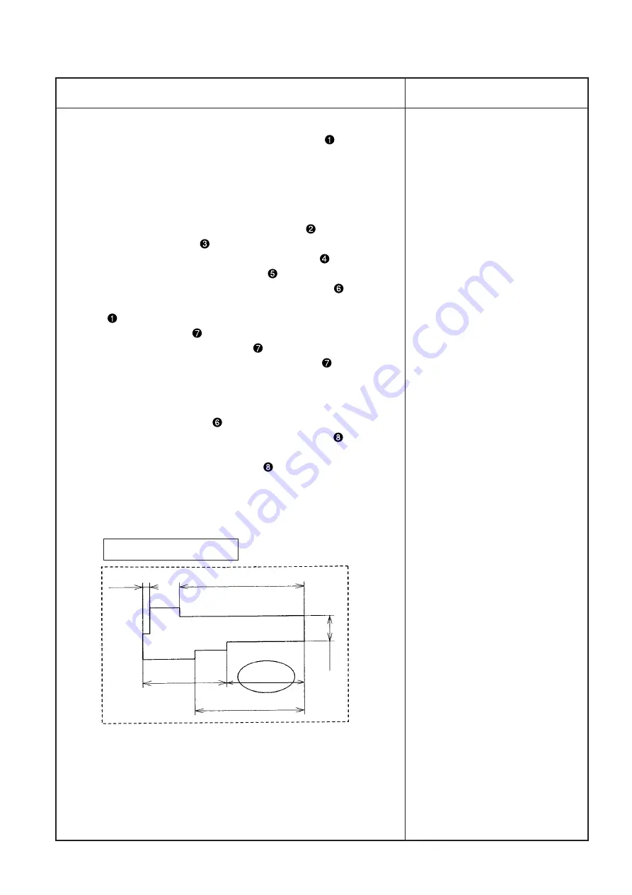
The initial position of the moving knife
is defined when the distance
is 26.8
±
0.2mm between tip of the moving knife
and the bed
groove. (At that time, it is possible to use an accessory adjusting
gauge.)
6. While the state of 5. above is maintained, tighten the moving knife
driving arm tightening screw
. (Tightening torque: 5.88 to 6.86N•m
(60 to 70kgf•cm)) For the moving knife driving arm
in vertical
directions at that time, the gap shall be 1.0
±
0.2mm between bottom
surface of the moving knife driving arm
and the top surface of the
thread trimming cam.
Subsequently, perform “9) Adjustment of gap between the moving
knife driving arm and the moving knife driving arm stopper”.
Adjustment Procedure
Results of Improper Adjustment
Adjusting gauge (accessory)
2.4
43.0
(t = 0.6)
29.0
26.8
37.8
9.0


