– 81 –
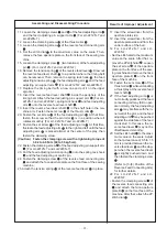
1) Removal Procedure of Aperture Plate
1. Remove the conversion link hinge screw
.
2. Loosen the set screw
(four locations) on the conversion link base
and remove the conversion link base
.
3. Loosen the 2P cylinder set screw
and remove the 2P cylinder
.
4. Loosen the cylinder connecting bar hinge screw nut
of the re-
verse feed cylinder
and remove the cylinder connecting bar hinge
screw
.
5. Loosen the set screw
(three locations) of the cylinder set plate
and remove the cylinder set plate
.
6. Remove the aperture plate set screw
(four locations) and remove
the aperture plate
.
2) Attachment Procedure of Aperture Plate
1. Attach the aperture plate
with the aperture plate set screw
(four locations).
2. Attach the cylinder set plate
temporarily with the cylinder set plate
set screw
(three locations).
3. Attach the cylinder connecting bar hinge screw
of the reverse
feed cylinder
and fasten the cylinder connecting bar hinge screw
nut
.
4. Adjust the cylinder set plate
and attach it so that it is parallel with
the head of the machine (in the direction of arm shaft), and that the
cylinder connecting bar
is parallel with the shaft center of the re-
verse feed cylinder
. Then fasten the cylinder set plate set screw
.
5. Attach the 2P cylinder
temporarily with the 2P cylinder set screw
.
6. Adjust the conversion link base
and attach it so that the 2P cylin-
der connecting link
is parallel with the shaft center of the 2P cylin-
der
. Then, fasten the conversion link base set screw
and fas-
ten the 2P cylinder set screw
.
7. Fasten the conversion link hinge screw
.
3) Adjustment of 2P Cylinder Connecting Link
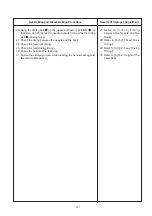
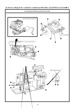
1. Connect air hoses to all the air cylinder couplings.
2. Arrange the air route.
3. Loosen the eccentric pin set screw
(two locations).
4. Align the notch of the eccentric pin
in the direction of the fulcrum
shaft of the conversion link
.
5. Turn the eccentric pin
in the direction A or B and move the 2P
cylinder connecting link
to the right and left by hand. Then stop it
when backlash is felt and fasten the eccentric pin set screw
.
Adjustment Procedure
Results of Improper Adjustment
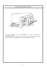
6’ Confirm that the feed regulator
link
projects from the center
of the long hole section of the
aperture plate
. If the projec-
tion point is deviated from the
center, adjust the 2P cylinder
position to the right or left and
adjust the conversion link base
again.
1’ Connect the air hoses so that
the seal No. of the air hose is
corresponding to the coupling
No.
5’ Direction A: Backlash increased
Direction B: Backlash de-
creased
* Adjust it so that backlash is
minimized.


