– 93 –
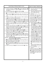
11. Loosen the clamping screws
and
of the feed adjusting arm
and the feed adjusting pin support arm
(For LU-2212N-7 and
LU-2220N-7).
12. Loosen the clamping screw
of the thrust collar
.
13. Loosen the clamping screw
of the reverse feed connecting arm
.
14. Set the stitch dial
to the maximum value on the scale. Then,
remove the face aperture plate on the front face of the sewing ma-
chine.
15. Loosen the clamping screw
(two locations) of the feed adjusting
pin
. (For LU-2212N-7 and LU-2220N-7)
16. Remove the tension spring
of the reverse feed lever
. Draw out
the reverse feed lever shaft
to a position where the timing belt
can be removed. Then, remove the spring rack hook
, the feed
adjusting tension spring
, the feed adjusting arm
and the feed
adjusting pin support arm
(For LU-2212N-7 and LU-2220N-7).
17. Replace the timing belt with a new one and put it on the upper
sprocket.
18. Insert the reverse feed lever shaft
inside the periphery of the
timing belt. Attach the feed adjusting pin support arm
(For LU-
2212N-7 and LU-2220N-7), spring rack hook
and feed adjusting
arm
onto the reverse feed lever shaft
.
19. Insert the reverse feed lever shaft
in the shaft hole in the ma-
chine arm. Fasten the set screw
of the thrust collar
.
20. Fasten the set screw
of the feed adjusting pin
. At that time,
fasten the screw so that the pin roller
is in a position where it
rotates smoothly. (For LU-2212N-7 and LU-2220N-7)
21. Fasten the set screw
of the feed adjusting arm
. At that time,
fluctuate the feed adjusting arm
to the right and left until the feed
adjusting arm
is placed almost at the center of the play, then
fasten the clamping screw.
(Caution)
Fasten the clamping screw with a tightening torque of
3.92 to 4.9 N•m (40 to 50 kgf•cm).
22. Fasten the clamping screw
of the feed adjusting pin support arm
(For LU-2212N-7 and LU-2220N-7).
23. Put the feed adjusting tension spring
onto the spring rack hook
and the feed adjusting eccentric pin.
24. Fasten the clamping screw
of the reverse feed connecting arm
and attach the face aperture plate on the front face of the sewing
machine.
25. Attach the tension spring
of the reverse feed lever
in place.
Assembling and Disassembling Procedure
Results of Improper Adjustment
11’ Insert the screwdriver from the
aperture plate side.
12’ Insert the screwdriver from the
aperture plate side and from the
under surface of the bed.
14’ F o r L U - 2 2 1 2 N - 7 a n d L U -
2220N-7:
• Set the stitch dial to the maximum
value on the scale. After that, re-
move the 2P stitch dial
. Loosen
the set screw
of the aperture
plate on the front face of the sew-
ing machine and remove the face
aperture plate B
on the front
face of the machine.
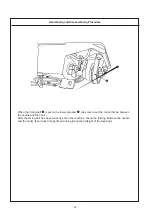
19’ Fasten the set screw
of the
thrust collar
while eliminating
a thrust play at the reverse feed
lever shaft
.
21’ If the feed adjusting arm
is
not correctly positioned, the feed
connecting rod may fail to oper-
ate normally, the feed adjusting
arm
may interfere with the in-
ner wall of the arm, and the feed
adjusting arm
may be pushed
against the side face of the feed
crank stud. In this case, the re-
verse feed lever
may not be
lifted/lowered smoothly.
23’ Set the stitch dial
to the maxi-
mum value on the scale. Adjust
so that a clearance of 0.5 to 1.5
mm is provided between the re-
verse feed lever
and the stop-
per when the reverse feed lever
is slightly pushed down, and
then fasten the clamping screw
.
(Refer to [3.-(8) Position of the
Reverse Feed Connecting Arm]
for further details.
24’ F o r L U - 2 2 1 2 N - 7 a n d L U -
2220N-7:
• Fasten the clamping screw
of
the reverse feed connecting arm
and attach the face aperture
plate B
on the front face of the
machine. After that, attach the 2P
stitch dial
.


