

ii
CONTENTS
.........................................................................................2
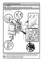
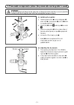
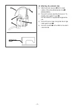
3. Pneumatic components (when the pneumatic center guide is used)
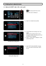
4. Setting the incidental device (pneumatic center guide)
............................................5
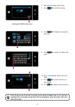
4-1. Setting the ON/OFF status of the center guide
...................................................5
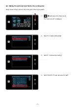
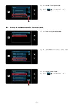
4-2. Setting the optional input for the the center guide
.............................................7
4-3. Setting the optional output for the center guide
................................................8
CAUTION
This Instruction Manual for the PLC-2760NV only describes their differences from the stan
-
dard models (PLC-2760V).
For safety-related information, carefully read and fully understand "Safety precautions"
described in the Instruction Manual for the standard models before using your sewing ma
-
chine.


