background image

– 3 –

WARNING :

To protect against possible personal injury due to abrupt start of the machine, be sure to start the 

following work after turning the power off and ascertaining that the motor is at rest.

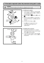
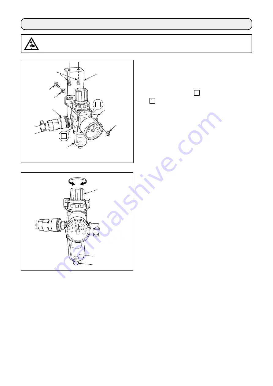
(1)  Installing the regulator

1)  Install regulator (asm.) 

 on mounting plate 


with screw 

, spring washer 

 and nut 

 which 

are supplied with the unit.
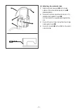
2)  Attach joint 

 to inlet 

1

. Attach joint 

 to outlet 

2

.

3)  Attach mounting plate 

 on the undersurface of 

the table with accessory screws 

 supplied with 

the plate.

4)  Connect the 

ø

6 air tube to joint 

.

  *  Screw 

 which is supplied with the unit:


Thread diameter M5; Length: 12 mm

 (SM6051202TP)

(2)  Adjusting the air pressure

1)  The operating air pressure is 0.5 to 0.55 MPa.
 

Adjust the air pressure using air pressure regulat-
ing knob 

 of the filter regulator.

2)  In the case fluid accumulation is observed in 

A


section of the filter regulator, turn drain cock 

 to 

drain the fluid.

Decrease

Increase

A

1

2

3. Pneumatic components (when the pneumatic center guide is used)

Summary of Contents for PLC-2760NV

Page 1: ...PLC 2760NV INSTRUCTION MANUAL ...

Page 2: ...nter guide 5 4 2 Setting the optional input for the the center guide 7 4 3 Setting the optional output for the center guide 8 CAUTION This Instruction Manual for the PLC 2760NV only describes their differences from the stan dard models PLC 2760V For safety related information carefully read and fully understand Safety precautions described in the Instruction Manual for the standard models before u...

Page 3: ...al feed control Electronic control Lubricating oil JUKI New Defrix Oil No 1 equivalent to ISO standard VG7 or JUKI MACHINE OIL No 7 Number of patterns Sewing pattern 99 patterns For the polygonal shape sewing as many as 10 patterns can be registered Cycle sewing pattern 9 patterns Custom pitch pattern 20 patterns Condensation custom pattern 9 patterns Noise Equivalent continuous emission sound pre...

Page 4: ... following the order as illustrated in the figure If you want to perform thread trimming at a position where no material exists it is necessary to change thread guide with the suitable thread guide The thread guide to be used instead of the current one is supplied with the unit as an accessory Part number of replacement thread guide 40034675 Left hand needle thread Right hand needle thread 2 Threa...

Page 5: ...3 Attach mounting plate on the undersurface of the table with accessory screws supplied with the plate 4 Connect the ø6 air tube to joint Screw which is supplied with the unit Thread diameter M5 Length 12 mm SM6051202TP 2 Adjusting the air pressure 1 The operating air pressure is 0 5 to 0 55 MPa Adjust the air pressure using air pressure regulat ing knob of the filter regulator 2 In the case fluid...

Page 6: ...le with accessory screw SK3452001SE 2 Connect the ø6 tube described in step 4 in 1 Installing the regulator to joint Cut the ø6 tube to an appropriate length before use 3 Connect the ø4 air tube coming from the air type center guide to joint 4 Connect connector to the CN59 on the electri cal control box ...

Page 7: ... The Incidental device setting screen is dis played When the device setting of which is to be changed is selected the setting screen for the selected device is displayed 4 Select 1 Center guide to display the Center guide setting screen Incidental device setting screen 5 Select H001 Function ON OFF to display the Center guide function ON OFF setting screen Center guide setting screen ...

Page 8: ...he S056 center guide 10 Then set the ON OFF status of the center guide 11 Press to confirm the value you have entered 12 Press to display the sewing screen If the pneumatic center guide does not function just by setting its ON OFF status set the optional in put output of the center guide as described in the next paragraph to enable the function of the pneu matic center guide ...

Page 9: ...ter guide Assign the switching function of the center guide to the 6 gang switch 1 held pressed for three second The mode screen is displayed 2 Select 19 Optional I O setting 3 Select 1 Optional input setting 4 Select INPUT6 Thread clamp switch input ...

Page 10: ... input 6 Press to confirm the selection 4 3 Setting the optional output for the center guide 1 Select 2 Optional output setting 2 Select OUTPUT11 Function is not provided 3 Select o25 Center guide 4 Press to confirm the selection ...

Reviews: