background image

 15 

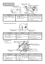
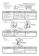
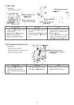
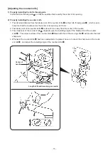
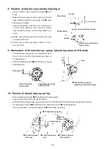
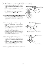
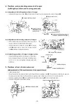
[Adjusting the counter knife]

1)


Properly installing the knife thread guide

Install the knife thread guide 

 so that the needle enters exactly the center of its opening.

2)  Properly installing the counter knife

1. The standard distance from the blade point of the counter knife 

 to the knife thread guide 

, which is posi-

tioned so that the needle enters the center of its opening, is 0.5 mm.

2. The blade point of the counter knife 

 is about 4 mm away from the center of the needle.

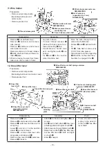
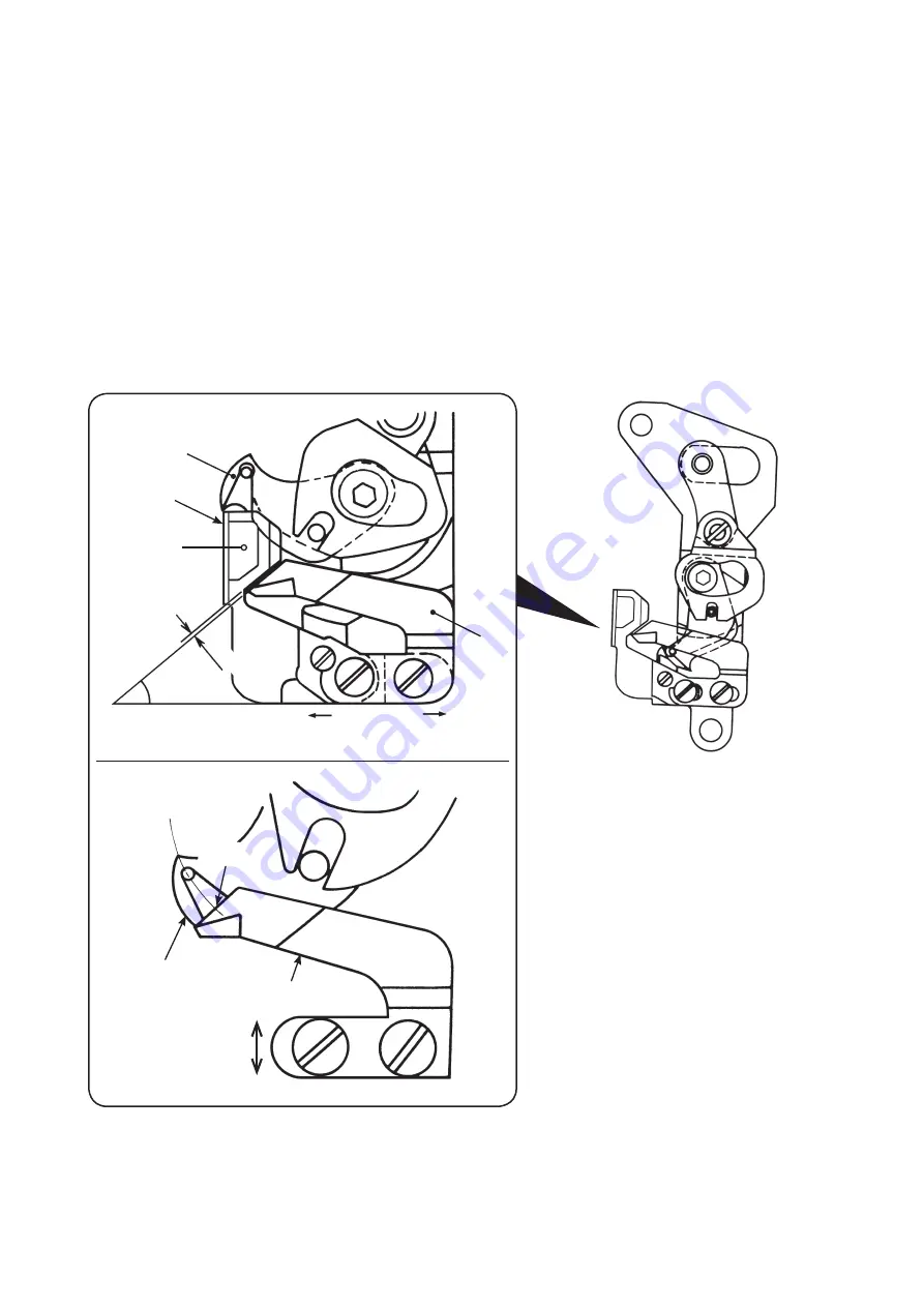
3. The sharpness of the counter knife 

 depends upon the installing angle of the blade point of the counter 

knife 

. The proper overlap of the counter knife 

 blade with that of the moving knife 

 will provide the best 

sharpness.

4. Whenever the counter knife 

 has been readjusted or replaced, be sure to check the sharpness of the count-

er knife 

, and adjust the installing angle of the counter knife 

.

Short

Center of 

needle

Long

Length of thread remaining on needle

0.5 mm

Center 

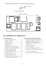
Summary of Contents for TL Series

Page 1: ...SERVICE MANUAL TL series 1 NEEDLE LOCKSTITCH SEWING MACHINE WITH AUTOMATIC THREAD TRIMMER FOR PROFESSIONAL No 00 40175681 ...

Page 2: ...id the risk of fire electric shock injury to persons or damage to components especially keep the following When disassembling assembling or adjusting the sewing machine remove the power plug When assembling be careful about the electrical cord being caught with other components damage to the covered parts of the cord or miswiring When replacing the part s use the genuine part s ...

Page 3: ...2 Hook DB type horizontal full rotary hook 3 Pressing pressure adjustment Stepless adjusting screw with pressing pressure indicator method 4 Lighting device Built in face cover Switch Slide type Lamp LED lamp 5 Needle thread post Two posts for small thread spool and large thread spool Thread guide of thread post is of draw out type and capable of one touch threading 6 Bobbin thread winder One touc...

Page 4: ...n stop can be performed by half rotation of main shaft when operating switch for a short period of time When switch is continuously held ON sewing machine continuously runs at a speed of 80 sti min until switch is turned OFF 5 Prevention of reverse setting of needle Needle is attachable to normal direction only 6 Motor protection Overcurrent When motor is locked for 0 5 to 1 second due to sudden o...

Page 5: ...13 2 Moving knife arm installing plate mas asm 13 3 Moving knife base mas asm 14 4 Thread trimming solenoid mas asm 14 Indicating needle of presser spring regulator Face cover Pressure indicating plate Thread take up thread guide Thread take up spring Presser bar connection thread guide LED lamp Needle bar thread guide Needle bar thread bracket Presser spring regulator Thread guide base Side cover...

Page 6: ... torsion in presser spring regulator Align precisely slit portion with con vex portion Do not press each lead wire Disassembly Assembly Point Remove four setscrews and remove belt cover Remove three setscrews and remove motor cover Attach belt cover and tighten setscrews Attach motor cover and tighten setscrews There should be no difference in level between belt cover and front face of frame Make ...

Page 7: ... set screw and remove circuit board Press play of circuit board to at tach circuit board to the front side and tighten two setscrews Insert each lead wire into con nectors Read the note and understand it There are color indications on the circuit board for inserting connectors Disassembly Assembly Point Remove cord guide plate set screws and 1 in previous item and cut clip band Loosen cord presser...

Page 8: ...and spring to thread tensioner asm and attach it to frame Then fix it with setscrew Tighten adjusting plate set screw Place upward the scale of thread tension disk presser See items 9 and 10 on page 19 for adjustment of pressure and thread take up spring of stroke Disassembly Assembly Point Remove setscrew Remove cord guide plate setscrew and remove cord guide plate asm Remove spring support Move ...

Page 9: ...move since secrew mark is attached Attach regulator screw Set lever to frame and then set connection Attach spring when setting presser bar from upper side Set spring under indicating needle Lower lever and temporarily tighten it at the position where top end of protrudes approximately 4 mm from frame For the adjustment see item 3 on page 18 Needle should not interfere with presser foot Disassembl...

Page 10: ...g shaft Remove and together with needle bar crank Set needle bar crank to thread take up attach it onto main unit and tighten setscrews 2 pcs Set to enter thread take up supporting shaft to at tach it onto frame and tighten setscrew Tighten setting portion flat por tion of needle bar crank with screw No 1 Press shaft to frame side while viewing the torque and tighten setscrew Disassembly Assembly ...

Page 11: ... Point Loosen two setscrews and re move the dial Be careful since pin jumps may not be removed Stopper screw SM8031400TP Turn regulating screw full to the right Assemble stitch dial with its scale 0 up and tighten screw 2 pcs There should be no play in feed regulator when operating lever When scale is 0 Loosen stopper nut Make stopper screw strike against reg ulating screw and tighten nut Disassem...

Page 12: ...hine bed Pass the wire through full re verse side of stitch dial Contact and with each oth er For tube has to come out by 13 mm from tube presser Tube presser and tube regarding should be on the same face See item 5 on page 28 for Disassembly Assembly Point Remove snap pin Remove setscrews and remove Remove setscrew and take out le ver spring Lower and turn it to the position where can be removed ...

Page 13: ...turn to find a place where backlash in hook driving shaft pulley is large Press and push out bush ing to the right side Draw out and and remove following the point of Do not make a flaw on E ring groove when removing E ring Enter hook driving shaft pulley Enter eccentric shaft and Set E ring Remove the play in hook driv ing shaft with and tighten setscrew B Turn shaft slit to adjust backlash in pu...

Page 14: ...ling DF adjusting arm asm Place E ring to drop feed knob Assemble drop feed knob shaft with setscrew It is easy to remove spring when drop feed knob is set to NOT FEED side Disassembly Assembly Point Loosen hand lifter lever shaft setscrew Insert M4 screw into tapped hole in hand lifter lever shaft by 3 to 4 screw threads Hold screw head and draw out the screw At the same time also draw out hand l...

Page 15: ... to hole Hook moving knife arm spring Set looper link and attach E ring washer etc Place looper in the center of inner hook and securely tighten See item 4 2 on page 28 for adjustment of looper moving amount Disassembly Assembly Point Remove E ring Do not remove moving knife link Remove together with moving knife arm installing plate Remove nut on the left side only Remove thread trimmer clutch pl...

Page 16: ...tighten it with setscrews Adjust clearance between pin at top end of thread trimmer auxil iary link and thread trimmer aux iliary cam to 0 5 to 1 0 mm and securely tighten setscrews Fix thread trimmer solenoid link A with eccentric shaft wash er and E ring See item 2 on page 23 and item 3 5 on page 24 for the adjustment Move thread trimmer solenoid asm to the left and right so that pin at top end ...

Page 17: ...ening is 0 5 mm 2 The blade point of the counter knife is about 4 mm away from the center of the needle 3 The sharpness of the counter knife depends upon the installing angle of the blade point of the counter knife The proper overlap of the counter knife blade with that of the moving knife will provide the best sharpness 4 Whenever the counter knife has been readjusted or replaced be sure to check...

Page 18: ...or AC220V 240V Plug socket MAIN circuit board CN9 3 VR for speed limiting Description MAIN circuit board Cord color Terminal Pin Motor CN7 1 Blue 3 Brown 5 Black Power connecting wire CN9 1 Blue 2 Brown Transformer CN8 1 Yellow secondary side 2 Yellow AC 22V 19 8V 3 Red 4 Red LED lamp CN2 1 Red 2 Black Bobbin winder SW CN1 1 Purple 2 Black 3 Gray MP detection circuit CN6 1 Red board 2 White 3 Blac...

Page 19: ...of threader hook 23 Automatic thread trimmer mechanism 1 Positioning of moving knife arm installing plate adjustment of position of moving knife 24 2 Installing position of thread trimmer solenoid moving amount of thread trimmer cam contactor shaft 24 3 Thread trimmer cam timing needle to cam position 25 4 Position and protruding amount of looper left right position and adjustment of movement 28 5...

Page 20: ...bar connection setscrew Position of standard Upper engraved line A on needle bar aligns with bottom end of needle bar bushing when needle bar is at lower dead point 3 Height of presser foot Adjust the height in the state that hand lifter lever is raised Clearance provided between top surface of throat plate and lower face of presser foot is 7 0 0 5 mm Perform adjustment with presser bar connection...

Page 21: ...k and left edge of needle to 0 to 0 2 mm when needle bar lifts by 2 17 mm from its lower dead point Check clearance between needle and hook and tighten setscrews Remove bobbin case positioning finger to im prove the work Standard of position of 2 mm from lower dead point of needle bar is that of engraved lines to on needle bar Lower dead point Position of lifting 2 mm 7 Clearance between needle an...

Page 22: ...ead guide as shown in the figure below Perform adjustment with thread take up spring adjusting plate 10 Tension of thread take up spring Pass needle thread up to thread tensioner thread guide Lower presser foot and draw needle thread Adjust tension of thread take up spring to 0 176 to 0 245N when thread take up spring starts lowering For adjustment loosen thread tensioner setscrew and turn thread ...

Page 23: ...obbin winder clutch plate and clutch plate spring support and temporarily tighten setscrew 2 Bobbin winder ON state Make sure that bobbin winder clutch plate comes in contact with inner ring of clutch plate spring support and securely tighten thread trimmer clutch plate link collar setscrew Bobbin thread Adjusting screw Bobbin case To come in contact with each other Bobbin winder ON Bobbin winder ...

Page 24: ...t base adjusting plate when bobbin winding shaft is OFF Then tighten micro SW setscrew Adjustment of amount of bobbin thread wound round bobbin How to adjust 1 Tighten bobbin winder switch contactor plate with setscrew at the position where bobbin winder switch is turned OFF when amount of bobbin thread wound round bobbin becomes 18 mm in diameter Bobbin winding shaft base adjusting plate Bobbin w...

Page 25: ...le eyelet is 0 to 0 1 mm when threader hook is turned 3 Insert hexagonal wrench key 1 5 mm from adjustment hole of threader support plate and slightly loosen needle bar guide setscrew When hook is lower move needle bar guide upward and temporarily tighten it When hook is higher move needle bar guide downward and temporarily tighten it Perform adjustment while confirming position in terms of needle...

Page 26: ...2 Installing position of thread trimmer SOL solenoid Move thread trimmer solenoid asm to the right and left to adjust so that clearance between thread trimmer auxiliary link and thread trim mer auxiliary cam is 0 5 to 1 0 mm and tighten it with setscrews When thread trimmer solenoid asm is set to ON it has to interlock thread trimmer auxiliary cam Moving knife base Moving knife arm installing plat...

Page 27: ...rimmer cam contactor shaft to groove in thread trimmer cam Slightly pressing thread trimmer cam to hand wheel side turn it in reverse direction Tighten thread trimmer cam with setscrews at place where idling term of cam groove place where rotation is hindered is finished 3 3 Positioning of roller holding cam Turn pin of link support plate and make it come in contact with concave portion of roller ...

Page 28: ...nt of eccentricity with thread trimmer clutch plate collar adjustment of clearance between roller holding cam and link arm support plate and ad just clearance to 1 to 3 mm Thread trimmer clutch plate collar Link arm support plate Thread trimmer solenoid link A Roller holding cam 1 to 3 mm Thread trimmer clutch plate collar A2435033000 Looper link arm asm A1727D250A0A Thread trimmer solenoid link A...

Page 29: ...shaft caulked in moving knife roller arm enters groove in thread trimmer cam Press thread trimmer contactor shaft ⓐ section of moving knife roller arm to make it come in contact with moving knife arm asm Insert a clearance gauge of 0 5 mm to contact part of moving knife roller arm asm and looper link arm asm and press looper link arm asm to moving knife roller arm asm In aforementioned state make ...

Page 30: ...er and looper installing base is 0 5 to 1 0 mm and tighten stopper plate with setscrew 5 Position of nut of wire setscrew Adjustment of thread tension disk open close Lower presser foot Move thread trimmer solenoid link A with thread trimmer auxiliary cam Thread tension disk has to open at the time when roller rides on thread trimmer auxiliary cam Disk rise of 0 5 to 0 7 mm at scale 3 5 Perform ad...

Page 31: ......

Page 32: ... JAPAN PHONE 81 42 357 2341 http www juki com 000316 Copyright 2016 JUKI CORPORATION All rights reserved throughout the world The description covered in this Service Manual is subject to change for im provement of the commodity without notice ...

Reviews: