11
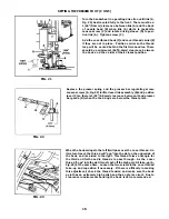
FIG. 8
TIMING THE NEEDLES TO THE LOOPER
To visually check the timing of the needles to the looper, turn the
handwheel in operating direction until the needle bar has reached
its lowest position and has risen 5/32" (4.0mm). At this time the looper
point should appear at the same relative position to the needles
whether rotation of handwheel is clockwise or counterclockwise.
INSTRUCTIONS FOR USING
SYNCHRONIZING GAUGE 21227CG
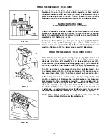
Turn the handwheel until the needle bar is at its lowest point. Loosen
presser bar regulating screw (A, Fig. 8) and insert needle bar setting
block (B) under the head of the screw (A) with stop screw (C) above
needle bar (D). Tighten screw (A).
The long portion of the looper clamp and height gauge (E, Fig. 8) laid
on its side is the 5/32" (4.0mm) gauge used to set the distance
between stop screw (C) and the top of the needle bar (D) at its lowest
position. Tighten nut (F) to clamp stop screw (C) into place.
TIMING THE NEEDLES TO THE LOOPER (CONT.)
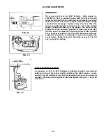
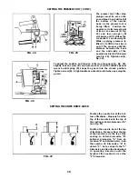
Attach the looper clamp and height gauge (A, Fig. 9) to the heal of
the looper by tightening screw (B). Turn the handwheel slowly in a
clockwise direction until needle bar (C) touches stop screw (D).
Loosen screw (E) and set synchronizing gauge rod (F) so the flat end
is on one of the lines in the center of the block (G). Tighten screw (E).
Turn the handwheel in the opposite direction until the needle bar
touches stop screw (D, Fig. 9). Synchronizing rod (F) should come to
the same line on block (G). The difference must not exceed one line.
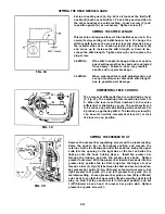
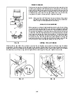
If the setting cannot be achieved, main shaft coupling (A, Fig. 10)
must be repositioned. Remove the crank chamber cover and gas-
ket. Loosen the three coupling screws (B). If synchronizing rod (F,
Fig. 9) moves more to the right while the handwheel is rotated in a
clockwise direction, the looper is too fast and the main shaft should
be retarded. If the rod moves more to the right when the handwheel
is rotated in a counterclockwise direction the looper is too slow and
the mainshaft should be advanced. Tighten screws (B, Fig. 10).
NOTE:
If the stationary Knife interferes with the synchronizing rod (F)
remove the knife to make the adjustment.
FIG. 9
FIG. 10
Summary of Contents for Union Special 36200L220-60
Page 6: ...6 THREADING...
Page 20: ...20...
Page 22: ...22...
Page 24: ...24...
Page 26: ...26...
Page 28: ...28...
Page 30: ...30...
Page 32: ...32...
Page 34: ...34...
Page 36: ...36...
Page 38: ...38...
Page 40: ...40...
Page 42: ...42...
Page 44: ...44...
Page 46: ...46...
Page 48: ...48...
Page 50: ...50...
Page 52: ...52...
Page 56: ......


