ENGLISH
74
DESCRIPTION
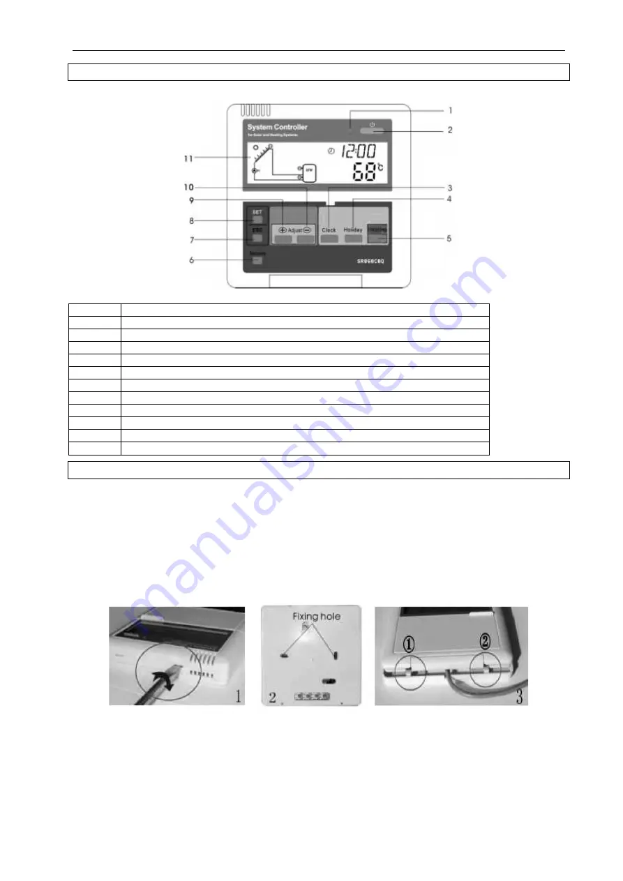
Position
Description
1
Voltage indication lamp
2
Power switch
3
Clock button
4
No holiday mode on this version
5
Manual auxiliary heating button
6
Reset button
7
ESC exit set-up button
8
SET confirm button
9
+ button for parameter change upwards
10
- button for parameter change downwards
11
LCD display
OPERATION
The controller must be installed indoors in a protected location away from electromagnetic fields. The
controller must be connected to 230 VAC, 50/60 Hz, with a fully isolating circuit-breaker with a minimum contact
distance of 3 mm, or in accordance with current regulations and requirements.
Installing the display unit
Remove the rear panel from the display unit using a screwdriver (see figure 1).
Mount the rear panel on the wall (see figure 2).
NOTE:
Do not drill holes in the rear panel.
Hang the display unit on the rear panel with the help of the grooves (pos. (1) and (2) in figure 3).
Installing the controller
NOTE:
The controller must be installed indoors in a sheltered position.
Installing the controller
Select a suitable location.
Mark out the position of the holes.
Drill the holes and insert the expansion screws.


