Product description
11
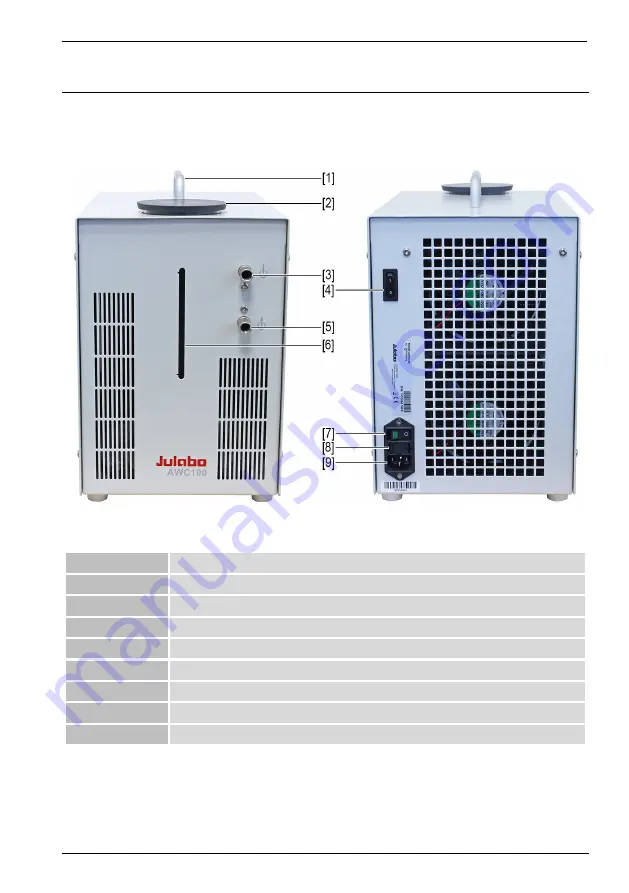
5.2 Operating and functional elements
The following figure shows the operating and functional elements and their
position on the unit.
Fig. 1: Control and function elements
1
Handle
2
Cooling water reservoir cover
3
Cooling water inlet hose connection
4
Cooling capacity switch
5
Cooling water outlet hose connection
6
Cooling water reservoir min./max. level indicator
7
Mains switch
8
Fuse 2 x T 1,25 A
9
Mains connection


