8 Device Manager
64
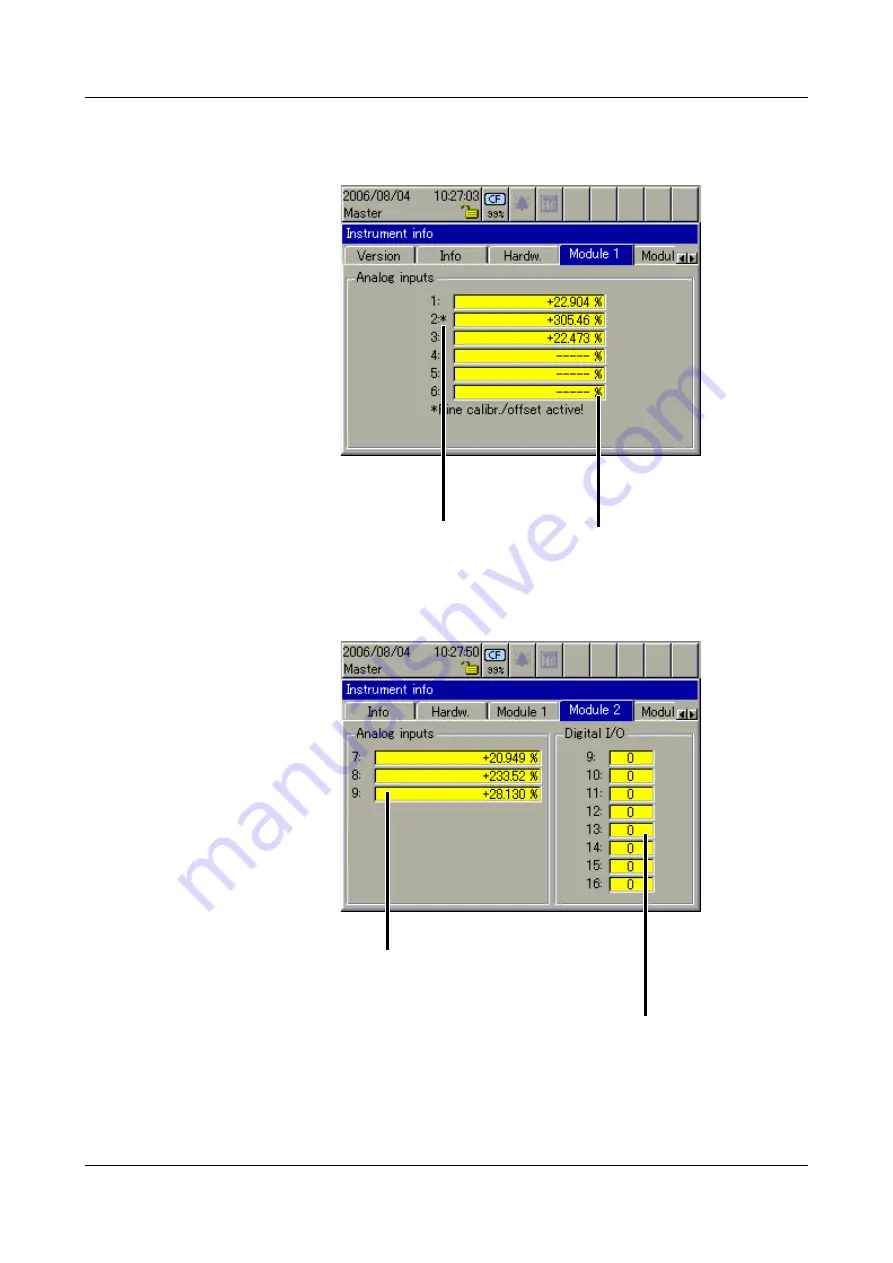
Module 1
The picture below shows a module that has been fitted with 6 analog inputs.
Depending on the hardware level, the picture may look different. Module 1 is in
the bottom module slot.
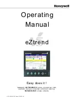
Module 2
The picture below shows a module that has been fitted with 3 analog inputs
and 8 binary inputs/outputs. Depending on the hardware level, the picture may
look different. Module 2 is in the middle slot.
Display of the current
analog values from module
The * indicates that an
offset or fine calibration is
active on this channel.
Display of the current
analog values from module
States of the binary inputs/
outputs (0 = not active).
Summary of Contents for LOGOSCREEN nt
Page 6: ...Contents...
Page 12: ...1 Introduction 12...
Page 18: ...2 Instrument Description 18...
Page 28: ...3 Operating Principle 28...
Page 46: ...4 Visualization 46...
Page 70: ...8 Device Manager 70...
Page 94: ...10 Web server 94...
Page 97: ...97 11 Appendix 345435 Job numbers A83737 A4555455 A455445 Personnel number 4576 7665...
Page 98: ...11 Appendix 98...
Page 104: ...12 Index 104...
Page 105: ......
Page 106: ......
Page 107: ......


