65
8 Device Manager
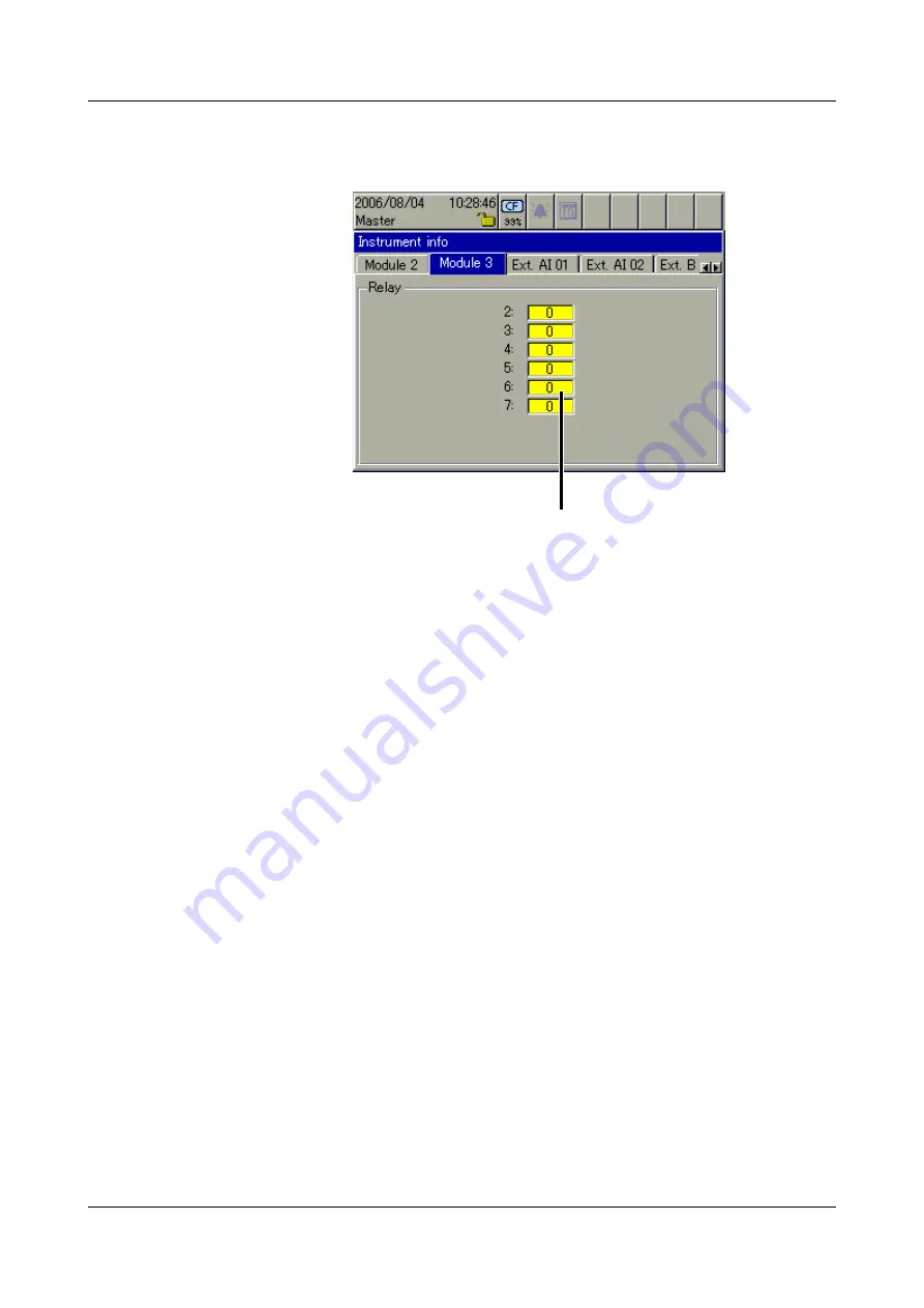
Module 3
The picture below shows a module that has been fitted with a relay card
(6 relays). Depending on the hardware level, the picture may look different.
Module 3 is in the top slot.
Ext. analog
input (AE) 1 — 2
The two windows show the current external analog inputs. External analog
inputs are read into the recorder via one of the interfaces (e.g. through the
Modbus Master function).
Ext. binary input
(BE)
The window shows the current external binary inputs. External binary inputs
are read into the recorder via one of the interfaces (e.g. through the Modbus
Master function). Unlike the internal binary inputs/outputs, external binary
outputs are not available.
Ext. texts
The three windows display the current external texts that can be integrated as
inscription or informational text in the batch protocols. External texts are read
into the recorder via one of the interfaces (e.g. through the Modbus Master
function).
Switching state of relays
(0 = not switched).
Summary of Contents for LOGOSCREEN nt
Page 6: ...Contents...
Page 12: ...1 Introduction 12...
Page 18: ...2 Instrument Description 18...
Page 28: ...3 Operating Principle 28...
Page 46: ...4 Visualization 46...
Page 70: ...8 Device Manager 70...
Page 94: ...10 Web server 94...
Page 97: ...97 11 Appendix 345435 Job numbers A83737 A4555455 A455445 Personnel number 4576 7665...
Page 98: ...11 Appendix 98...
Page 104: ...12 Index 104...
Page 105: ......
Page 106: ......
Page 107: ......


