37
5 Installation
4
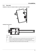
Move the cover (C) to the right (C3) until the side contacts of the neighboring module are
exposed. Then release the cover at the bottom using a screwdriver, press upward, and
remove from the DIN rail.
Note: The cover does not need to be removed from the DIN rail if there is sufficient space
to the side to move it at least 10 mm to the right.
5
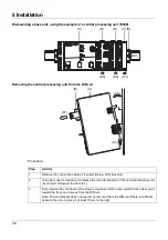
Move the modules (B) on the right next to the central processing unit (A) to the right (B4)
until the side contacts of the central processing unit are exposed.
➥
These modules are isolated from the voltage supply and the system bus.
6
Press the central processing unit (A) upward from underneath (A5), pivot off the DIN rail
toward the front (A6), and remove.
Step
Activity
Summary of Contents for mTRON T
Page 2: ......
Page 5: ...5 Contents 8 2 System expansion system version 02 71 8 3 Training courses seminars 72 ...
Page 6: ...Contents 6 ...
Page 50: ...5 Installation 50 ...
Page 62: ...6 Electrical connection 62 ...
Page 66: ...7 Startup and configuration 66 ...
Page 73: ......


