41
5 Installation
3
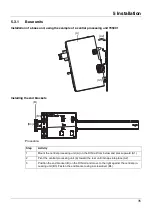
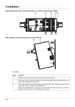
Move the modules (B) on the right next to the multichannel controller module that is to be
replaced (A) a minimum of 20 mm to the right (B3).
➥
These modules are isolated from the voltage supply and the system bus.
4
Move the multichannel controller module (A) to the right (A4) until the side contacts of the
neighboring module (here: central processing unit) – on the left, next to the multichannel
controller module that is to be replaced – are exposed.
➥
The multichannel controller module is isolated from the voltage supply and the system
bus. This is a prerequisite for the dismounting of the multichannel controller module.
5
If required, pull off the wired terminals (E) of the multichannel controller module (A) toward
the front (E5).
6
Insert a suitable screwdriver (F) into the unlocking slot of the multichannel controller mod-
ule (A6) and press upward (F7).
7
Pivot the multichannel controller module (A) upward off the DIN rail (A8) and remove it.
Step
Activity
Summary of Contents for mTRON T
Page 2: ......
Page 5: ...5 Contents 8 2 System expansion system version 02 71 8 3 Training courses seminars 72 ...
Page 6: ...Contents 6 ...
Page 50: ...5 Installation 50 ...
Page 62: ...6 Electrical connection 62 ...
Page 66: ...7 Startup and configuration 66 ...
Page 73: ......


