55
6 Electrical connection
6.3
Voltage supply
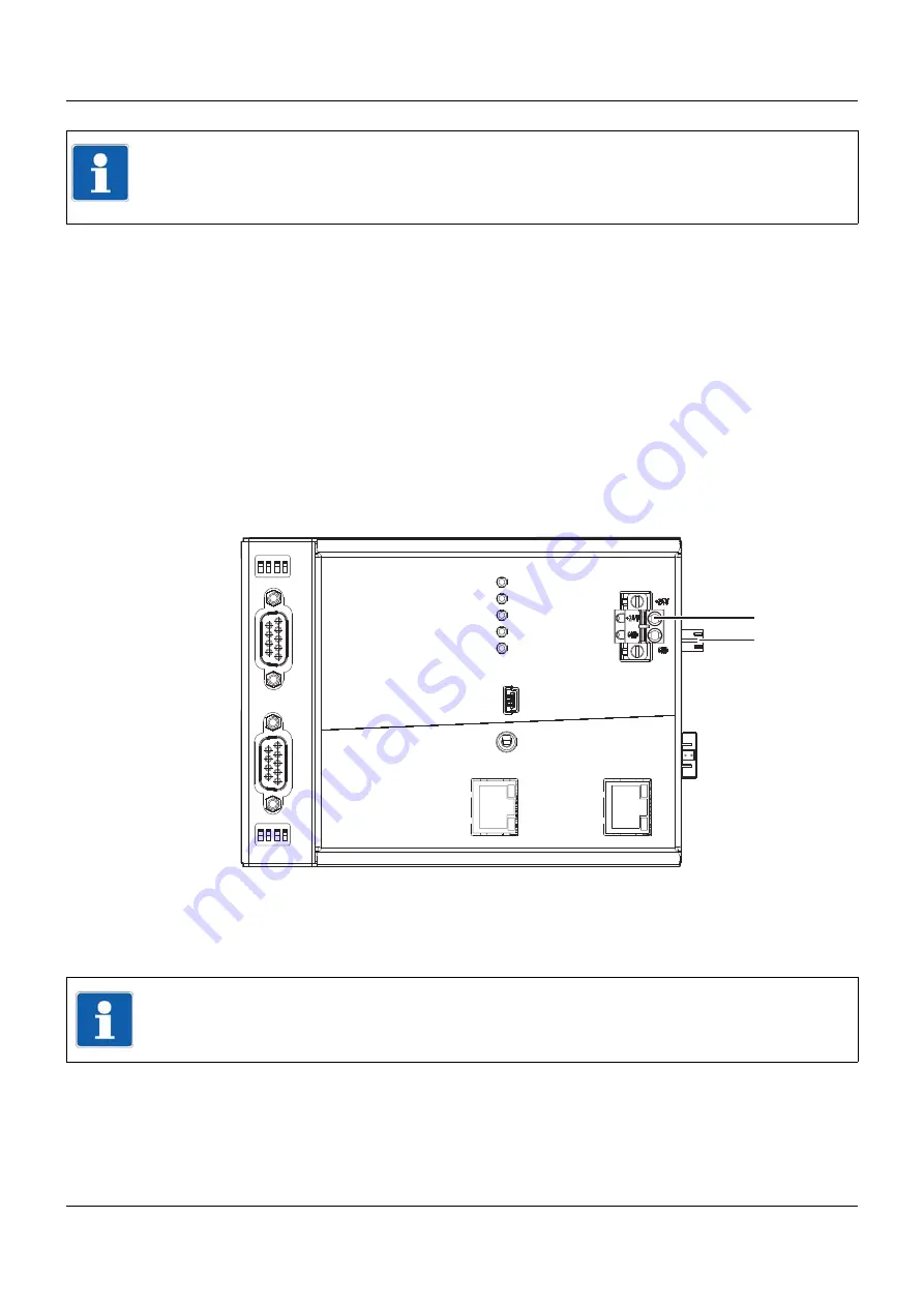
The DC 24 V voltage supply is provided by an external power supply unit and fed in via the
base unit (central processing unit) or a router module. For this purpose, these modules have a
2-pole terminal strip with Push-In technology that can be accessed from the front (1). The ter-
minal strip can be removed after releasing a screw connection.
The input/output modules are supplied with voltage via the side contacts (2) of the base unit or
router module.
The voltage supply for the multifunction panel – also DC 24 V – is to be fed in via a terminal
strip (11) on the multifunction panel. This also involves a 2-pole terminal strip with Push-In tech-
nology that can be removed after releasing the screw connection.
Voltage supply of a base unit, using the example of a central processing unit
The router module has identical connections to the voltage supply (note the reversed arrange-
ment of the +24 V and GND terminals).
NOTE!
The external voltage supply for the digital input/output module 12-channel and the voltage sup-
ply for controlling the digital inputs of this module must be switched on/off with a common dis-
connecting device (common electrical circuit).
Setup
LAN
Bus Out
Run
Stop
Reset
Power
Status
Bus Error
Com1
Com2
Com2
2
1
3
4
ON
2
1
3
4
ON
Com1
1
2
1
Voltage supply In, DC 24 V
2
Voltage supply Out, DC 24 V
NOTE!
Only use the installation instructions or the operating manual of the affected module for the
electrical connection. Follow the safety information stated there.
Summary of Contents for mTRON T
Page 2: ......
Page 5: ...5 Contents 8 2 System expansion system version 02 71 8 3 Training courses seminars 72 ...
Page 6: ...Contents 6 ...
Page 50: ...5 Installation 50 ...
Page 62: ...6 Electrical connection 62 ...
Page 66: ...7 Startup and configuration 66 ...
Page 73: ......


