background image

9

Service

Please note that all service must be carried out by a qualified 
person.  

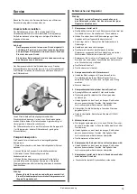
Adjustment of pressure switch

The working presure has ben preset from the factory, and it is 
normally not necessary to change this. 
However, if it is necessary to change the preset settings, the 
instructions mentioned below should be followed carefully. 

Warning! 


The compressor is constructed and approved 
for a max. pressure as stated under Technical 
Specifications - do not adjust to a higher pressure. 

Higher working pressure will reduce the lifetime of 
the compressor.

The compressor will stop at max. pressure (stop pressure) and 
start again at min. pressure (start pressure). The difference 
between max. and min. pressure is the differens pressure. 

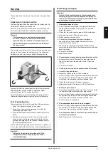
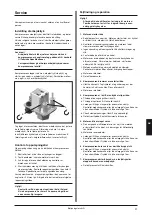
Unscrew the lid of the pressure switch. Adjust max. pressure 
adjusting the two springs marked A (clockwise: higher 
pressure). Adjust the two springs identically. 

Adjust the differens pressure adjusting the spring marked B 
(clockwise: higher differens pressure, lower start pressure.

Test of pumping time

The pumping time indicates the condition of the compressor. 

Check that there are no leaks in the system.
Empty the air receiver of compressed air so that the 
pressure gauge shows 0 bar.
Close the filter regulator and check that the drain valve is 
closed. 
Start the compressor and note the time it takes until it is 
turned off again by the pressure switch. Check that the  
pumping time agrees with the technical specifications for 
the actual compressor system.

Please note that the pumping time in this manual is given for 0 
to max pressure. Deviations from this result in deviating results.

Important! 

Always test the pumping time when cold. If the 
compressor is warm, the pumping time will be 
considerably longer. 

1.
2.

.

4.

Fault finding and repair

Important   


Switch off and isolate from electrical supply before 
removing any parts from the compressor. Empty air 
receiver of air before performing any operation on the 
compressors' pressure system.

1.  Compressor does not start

The air receiver is pressurized. The motor will start when 
the pressure has dropped to the preset start pressure. 
Empty the receiver.
Check that the mains supply agrees with the motor label. 
No power from mains. Check fuses and plug.
Bad connection or broken cable.
The motor is overheated and the thermal protection 
has switched it off. When cooled the motor will turn on 
automatically. Go to section 5.
The compressor has not been unloaded and there is back 
pressure on the piston. Ensure that the compressor is unloaded 
each time it stops.
The motor is blocked.
Defective capacitor.

2.  The compressor makes a buzzing sound but does not start

Leaky non-return valve. Dismount the pressure pipe and 
check if air leaks from the non-return valve. Clean and 
replace. 
The motor is blocked. 

3.  The compressor runs but the pressure does not increase

Intake filter clogged. Replace.
Non-return valve is clocked. Clean or replace.
Leaks in  fittings, tubes or pneumatic equipment. Check with 
soapy water or by letting unit stay over night disconnected 
from mains. Pressure drop should not exceed 1 bar.   
Check the piston gaskets. Replace if necessary.
Defective valve plate. Contact your JUN-AIR distributor.

5.  The motor gets very hot


The ambient temperature is too high. If the motor is installed 
in a cabinet sufficient ventilation must be ensured.
Leaks in  fittings, tubes or pneumatic equipment. Check with 
soapy water or by letting unit stay over night disconnected 
from mains. Pressure drop should not exceed 1 bar.  
The compressor is overloaded.

6.  The compressor runs even if no air is tapped

Leaks in  fittings, tubes or pneumatic equipment. Check with 
soapy water or by letting unit stay over night disconnected 
from mains. Pressure drop should not exceed 1 bar. 

7.   The compressor does not start at min pressure or does 

not stop at max pressure.

Defective pressure switch. Replace.

a.

b.
c.
d.
e.

f.

g.
h.

a.

b.

a.
b.
c.

d.
e.

a.

b.

c.

a.

a.

B

A

+

-

+

-

Operating manual

GB

Summary of Contents for 2 OF302-40M Series

Page 1: ...Operating manual Betriebsanweisung Betjeningsforskrift Compressor Model OF301 4M OF301 4MD2 OF302 4M OF302 4MD2 OF302 25M OF302 25MD2 2xOF302 40M 2xOF302 40MD2 3xOF302 40M 3xOF302 40MD3...

Page 2: ...ruckbeh lter gew hrt JUN AIR 5 Jahre Garantie Ausgenommen von Garantieleistungen sind Sch den die durch Gewalt falsche Bedienung nicht fachgerechte Reparaturen oder durch Verwendung nicht originaler E...

Page 3: ...specifications 23 Technische Daten Caracteristiques techniques Detalles t chnicos Technische gegevens Tekniske specifikationer Diagrams 28 Zeichnungen Dessins Diagramas Tekeningen Diagrammer Spare pa...

Page 4: ......

Page 5: ...air Do not pump combustible liquids or vapours with this product do not use it in or near areas with combustible or explosive liquids or vapours Do not use this unit near naked flames CAUTION To preve...

Page 6: ...t to ensure sufficient ventilation 1 2 6 5 4 3 1 Installation Note This product must be connected to a power supply branch protected by a fuse or circuit breaker with a rating of not less than 20 A in...

Page 7: ...l the temperature is below 30 C again Do not lubricate the oil less motor with oil as it will destroy important components Start Start the compressor with the green button The green lamp for compresso...

Page 8: ...k the fans Check that the fans at the back of the cabinet work They will start when the temperature exceeds 30 C and will run continuously until the temperature falls below 30 C i Check dryer If a dry...

Page 9: ...compressor Empty air receiver of air before performing any operation on the compressors pressure system 1 Compressor does not start The air receiver is pressurized The motor will start when the press...

Page 10: ...ng must be made on pressurised parts Safety valve Ensures that PS will not be exceeded Never adjust to a higher pressure than PS The capacity of the valve must be calculated in accordance with the vol...

Page 11: ...tzt werden VORSICHT Verletzungen verhindern Richten Sie den Luftstrom niemals direkt auf den K rper Stellen Sie den Kompressor au erhalb der Reichweite von Kindern auf Schalten Sie das Ger t keinesfal...

Page 12: ...uftzirkulation zu sorgen 1 2 6 5 4 3 1 Installation Hinweis Dieses Produkt muss um die Anforderungen der EMC Richtlinie 89 336 EEC zu erf llen an eine Spannungsversorgung mit einer Sicherung oder eine...

Page 13: ...chmieren Dies w rde Komponenten des Ger tes zerst ren Start Durch Bet tigen des gr nen Tasters starten Sie den Kompressor Die gr ne Lampe f r den Kompressorbetrieb leuchtet jetzt Der Ausgangsdruck kan...

Page 14: ...binetts durch um die Funktion der L fter zu berpr fen Die L fter starten bei einer Temperatur von 30 C und bleiben eingeschaltet bis diese Temp wieder unterschritten wird i Trockner berpr fen Ist der...

Page 15: ...ur drucklos sein 1 Kompressor startet nicht Der Beh lter steht unter Druck Kompressor startet erst bei Druckabfall bis zum Einschaltdruck Druck ablassen Stellen Sie sicher dass die Stromversorgung mit...

Page 16: ...Es soll verhindern dass der max Betriebsdruck des Beh lters berschritten wird Die Ausf hrung des Ventils richtet sich nach dem max Betriebsdruck des Kessels PS Der max Betriebsdruck des Beh lters Konf...

Page 17: ...af omr der med brandbare eller eksplosive v sker eller dampe Anvend ikke dette produkt i n rheden af flammer GIV AGT Undg skade Undg at sende luftstr m direkte mod en persons hoved og krop Ved anvend...

Page 18: ...str kkelig ventilation bag kabinettet monteres afstandsboltene 1 1 2 6 5 4 3 1 Installation Bem rk Dette produkt skal tilsluttes en str mforsyning med en forsikring p minimum 20 A for at sikre at krav...

Page 19: ...gget ikke er i drift indtil temperaturen er under 30 C igen Sm r ikke den oliefrie motor med olie da dette vil del gge vigtige dele Start Start anl gget med den gr nne knap Den gr nne lampe for motor...

Page 20: ...ungerer De starter n r temperaturen overstiger 30 C og k rer kontinuerligt indtil temperaturen atter er under 30 C i Kontroller t rrer Hvis anl gget er forsynet med t rrer vedligeholdes denne i henhol...

Page 21: ...motoren T m beholderen for luft f r indgreb i kompressor anl ggets tryksystem 1 Motoren starter ikke Beholderen st r under tryk Motoren starter f rst n r trykket er faldet til min arbejdstryk Udluft b...

Page 22: ...ke svejses p de trykb rende dele Sikkerhedsventil Skal sikre at PS ikke kan overskrides M aldrig indstilles h jere end PS Kapaciteten p ventilen skal v re beregnet efter den m ngde luft kompressoren l...

Page 23: ...1 m dB a 65 66 66 65 66 65 66 65 66 68 68 Neutral is required Available for operation at a higher pressure upon request Please note that operation at higher pressure will influence the life time Displ...

Page 24: ...at a higher pressure upon request Please note that operation at higher pressure will influence the life time Displacement is reduced by approx 18 20 on units with dryer D Min pressure required to ope...

Page 25: ...25M OF302 25MD2 Tank size liter 25 25 US gallon 6 6 6 6 Weight kg 78 83 lbs 172 183 Dimensions l x w x h mm 720 x 460 x 860 Inch 28 0 x 18 0 x 34 0 Pumping time 0 8 bar 0 120 psi 50 Hz sec 325 325 60...

Page 26: ...nsdauer des Kompressors beeinflusst Pression sup rieure sur demande Presi n mayor sobre demanda Hogere druk op aanvraag H jere tryk kan leveres Bem rk at h jere driftstryk vil p virke levetiden Neutra...

Page 27: ...80 50 Hz 60 Hz Model 2xOF302 60 50 40 30 1 2 3 0 4 5 6 7 8 bar Ltr min 2 0 1 5 cu ft min 0 20 40 60 80 100 120 psi 20 50 Hz 60 Hz 1 0 Model OF301 120 100 80 60 1 2 3 0 4 5 6 7 8 bar Ltr min 4 0 3 0 2...

Page 28: ...lectrical diagram OF301 and OF302 230 V 50 60Hz 6072860 6072862 Diagrams 6072861 Electrical diagram OF301 and 302 100 V 50 60 Hz and 120 V 60 Hz Electrical diagram OF301 and OF302 200 V 50 60 Hz Diagr...

Page 29: ...29 Electrical diagram OF301 12 24V DC with motor protection Electrical diagram OF301 and 302 3x400V 50 60Hz 6072864 6072867 6072866 Electrical diagram OF301 12 24V DC without motor protection Diagrams...

Page 30: ...30 6072960 Electrical diagram OF301 and 302 M D Diagrams...

Page 31: ...31 6073160 Electrical diagram 2xOF301 and 2x302 M D Diagrams...

Page 32: ...32 Electrical diagram 3x302 M D 6073250 Diagrams...

Page 33: ...81200 Motor compressor OF301 120V 60Hz 2881206 Motor compressor OF301 230V 60Hz 2881400 Motor compressor OF301 100V 50Hz 2881420 Motor compressor OF301 100V 60Hz 2881440 Motor compressor OF301 200V 50...

Page 34: ...ine 6984911 Mounting bracket C D 200 V Snapline 6984912 Front complete B MD 400V Snapline 6984913 Mounting bracket A M B M 200 V Snapline 6984915 Back B M 120V Snapline 6984916 Back B M 230V Snapline...

Page 35: ...ack 7167201 Plug 1 4 w o ring track 7167215 Plug 1 4 w M6 o ring track 7172805 Spacer for model OF300 M 7180000 Elbow 1 4 int ext KRG 7190000 Elbow 1 8 7598600 Y connection 1 8 3 x int 8008155 Bracket...

Page 36: ...36 Spare parts motor OF301 0070000 0080000 Spare parts motor OF302 Spare parts...

Page 37: ...37 Spare parts OF301 4M 0080120 Spare parts...

Page 38: ...38 Spare parts OF301 4MD2 0080121 Spare parts...

Page 39: ...39 Spare parts OF302 4M 0080122 Spare parts...

Page 40: ...40 Spare parts OF302 4MD2 0080123 Spare parts...

Page 41: ...41 Spare parts OF302 25M 0080130 Spare parts...

Page 42: ...42 Spare parts OF302 25MD2 0080131 Spare parts...

Page 43: ...43 Spare parts 2xOF302 40M 0080140 Spare parts...

Page 44: ...44 Spare parts 2xOF302 40MD2 0080141 Spare parts...

Page 45: ...45 0080150 Spare parts 3xOF302 40M Spare parts...

Page 46: ...46 0080151 Spare parts 3xOF302 40MD3 Spare parts...

Page 47: ......

Page 48: ...P O Box 97 Benton Harbor Michigan 49023 0097 USA www jun air com Phone 269 934 1216 Fax 269 927 5725 E mail jun air idexcorp com...

Reviews: