background image

4.2 Commissioning

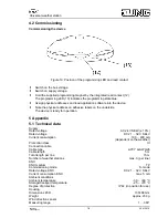
Commissioning the device

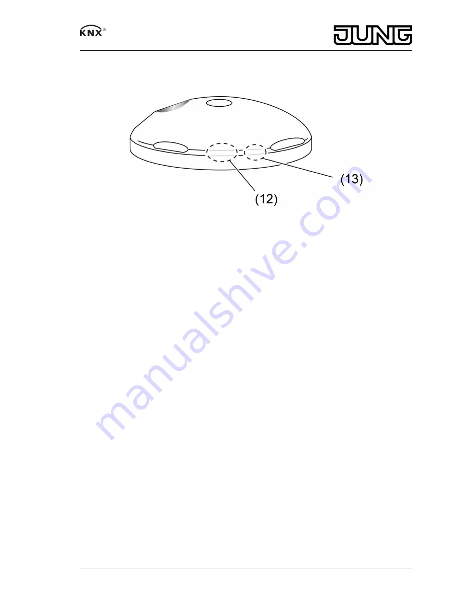
Figure 10: Position of the programming LED and reed contact

o

Switch on the bus voltage.

o

Switch on supply voltage.

o

Hold the supplied programming magnet by the integrated reed contact (12).
The programming LED (13) indicates the programming state blue.

o

Assign physical addresses and load application software into the device.

o

Note the physical address on adhesive labels on the underside.
The device is ready for operation.

5 Appendix

5.1 Technical data

Supply
Rated voltage

AC 24 V SELV (± 10%)

Rated voltage

DC 21 ... 32 V SELV

Current consumption

100 ... 400 mA

(dependent on the weather)

Protection class

III

Connection cable
Cable type

LiYCY 4xAWG26

Cable length

5 m

Total length per line

15 m

Number of weather stations

max. 3 (per line)

KNX
KNX medium

TP

Commissioning mode

S-mode

Rated voltage KNX

DC 21 ... 32 V SELV

Current consumption KNX

max. 5 mA

Ambient conditions
Ambient temperature

-30 ... +60 °C

Storage/transport temperature

-25 ... +70 °C

Degree of protection

IP 44 (in position for use)

Housing
Dimensions Ø×H

130×68 mm

Weight

approx. 230 g

Wind direction sensor
Measuring range

1 ... 360°

7/9

82590103
J:0082590103

30.01.2015

Universal weather station

Summary of Contents for 2225 WS U

Page 1: ...and fitted by electrically skilled persons Serious injuries fire or property damage possible Please read and follow manual fully These instructions are an integral part of the product and must remain...

Page 2: ...evaluation of weather data Wind speed Wind direction Precipitation Brightness Global radiation Twilight Temperature Relative air humidity and Air pressure Installation on the outside of buildings pref...

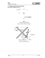
Page 3: ...1 Fitting and electrical connection Selecting the installation location Figure 3 Minimum distance to surfaces Figure 4 Avoid spray water 3 9 82590103 J 0082590103 30 01 2015 Universal weather station...

Page 4: ...weather station will be accessible In the case of flat roofs locate the weather station as close to the centre of the roof as possible Minimum distance to surfaces below the weather station 0 6 m fig...

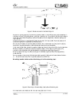
Page 5: ...se clamps are suitable up to a maximum mast diameter of 60 mm i If mounted on the supplied fastening arm do not mount the enclosed guide blade o Mast mounting Attach fastening arm to mounting mast usi...

Page 6: ...24 V brown GND i The sensor head is translucent Therefore do not stick or write on the sensor head Aligning the device Figure 9 Orienting the weather station o Align the sensor head in the appropriate...

Page 7: ...ical data Supply Rated voltage AC 24 V SELV 10 Rated voltage DC 21 32 V SELV Current consumption 100 400 mA dependent on the weather Protection class III Connection cable Cable type LiYCY 4xAWG26 Cabl...

Page 8: ...g range 300 1100 hPa Resolution 0 01 hPa Accuracy 0 5 hPa 20 C Humidity sensor Measuring range 0 100 rel humidity Resolution 0 1 rel humidity Accuracy 10 rel humidity 20 C abs humidity 0 400 g m Resol...

Page 9: ...mestra e 1 58579 Schalksm hle Telefon 49 23 55 8 06 0 Telefax 49 23 55 8 06 2 04 kundencenter jung de www jung de Service Center Kupferstr 17 19 44532 L nen Germany 9 9 82590103 J 0082590103 30 01 201...

Reviews: