© JUNG Hebe- und Transporttechnik GmbH
JKB revolving transport trolleys / JLF multi-purpose trolleys
- 43 -
English
1
2
M+P-44A-0026
Positioning of driving and steering gear
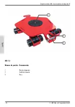
Item number
Description
1
Trolley
2
Steering system
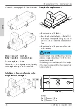
It is determined where the driving and steering gear
are positioned.
Here, the following rule applies:
The centre of gravity must be closer to the trolley. In
addition, it must lie within the triangle determined
between the support points of the transport trolley;
otherwise the transport load will tilt.
When lifting the transport load, it should be observed
that the edge which is opposite the jack acts like an
axis of rotation. The transport load rotates about this
during lifting.
The point for applying the jack had been determined
graphically as described above.
> Position trolley (1) under the transport load.
> Position steering system (2) under the transport
load.
WARNING
If positioned incorrectly, e.g. on or near the located
line, there is a danger of tipping, since the fulcrum can
move. The transported load will tip over uncontrollably.
There is a danger of injury.
4.2 Optional accessories
Risk of injury: Load must not be applied
to the drawbar. Dropping of the drawbar
can cause injury. Pay attention to the
correct load distribution and wear
protective clothing.
Transport trolleys can be joined with a connecting rod.
There is also the option of attaching a towing bar to
the trolley.
When using a towing bar, the dead weight of the
trolley increases.
WARNING
Attaching the optional accessory may result in bruises
and injuries. Always wear safety clothing.
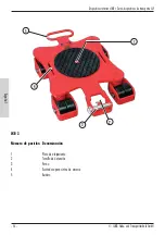
Item number
Description
1
Connecting rod
JKB 1.5-3; JKB 4-7.5
2
Connecting rod, M series
> Pull out the bolt from both trolleys.
> Push the connecting rod in between and secure this
to the trolleys.
1
2
M+P-44A-0067


