Art.-No.: 4071.0x LED, 4072.0x LED
Art.-No.: 8471.0x LED W, 8472.0x LED W
1 Product definition
1.1 Product catalogue
Description: Push-button BCU / Push-button BCU IP44
Use:
Sensor
Design:
FM (flush-mounted)
Art.-No.:
4071.0x LED, 4072.0x LED / 8471.0x LED W, 8472.0x LED W
1.2 Function
The KNX bus coupler push-button (push-button BCU) combines the functions of a simple push-
button sensor, in just one device. Rocker switches of various switch programs can be attached
to the bus coupler push-button, in which KNX operating functions can be integrated
conventionally into the electrical installations.
The bus coupler push-button must be configured with the ETS and put into operation. It is
suitable for installation in flush-mounted appliance boxes (device versions
407x.01 LED, 407x.02 LED) or for the IP44 splash-proof surface-mounting (device versions
847x.01 LED W, 847x.02 LED W).
Depending on the device version - 1-gang or 2-gang - rocker switches or two-circuit switching
rockers are used. In the "neutral position" device version, the rocker switch can be operated on
both sides (top or bottom). In the ETS, the operation concept can then be configured to rocker
function (the same KNX function on both control elements) or alternatively to push-button
function (the same or different KNX functions on the control elements). In the "neutral position"
version, the rocker switches are upright when they are not pressed.
In the "switch position" version, the rocker switch can only be operated on one side (e.g. at the
bottom) so that only push-button functions are executable. In this case, the rocker switch is
slanting when it is not pressed.
In the ETS, the KNX functions "Switching", "Dimming" and "Venetian blind" are configurable for
rocker switch operation concepts. In the pushbutton control concepts, the KNX functions
"Switching", "Dimming", "Venetian blind", "1-byte value transmitter" and "scene extension" are
configurable.
Two single-colour LEDs can be used for orientation lighting or for button-press display. In the
"neutral position" device version, the LED can also be used as a status indicator with the "rocker
switch" operation concept. In this case, the LEDs have their own 1-bit communication objects
for activation.
In the 1-gang push-button bus coupler, both LEDs always perform the same display function. In
the 2-gang device, the LEDs can perform different functions independent of each other.
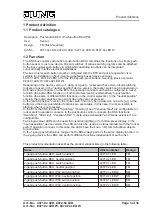
This product documentation describes the product variants listed in the following table...
Name
Article number
Design
1-gang push-button BCU, switch position
4071.01 LED
FM
1-gang push-button BCU, neutral position
4071.02 LED
FM
2-gang push-button BCU, switch position
4072.01 LED
FM
2-gang push-button BCU, neutral position
4072.02 LED
FM
1-gang push-button BCU IP44, switch position
8471.01 LED W
SM
1-gang push-button BCU IP44, neutral position
8471.02 LED W
SM
2-gang push-button BCU IP44, switch position
8472.01 LED W
SM
2-gang push-button BCU IP44, neutral position
8472.02 LED W
SM
Page 3 of 34
Product definition


