Art.-No.: 4071.0x LED, 4072.0x LED
Art.-No.: 8471.0x LED W, 8472.0x LED W
2.5 Operation
The KNX bus coupler push-button (push-button BCU) fulfills the functions of a simple push-
button. The device must be configured and put into operation using the ETS. In the
unprogrammed delivery state, the device does not function. Only the status-LEDs of the rockers
will be activated (see page 24).
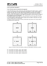
Depending on the device version - 1-gang or 2-gang - the device is installed with rocker
switches or two-circuit switching rockers. In the "neutral position" device version, the rocker
switch can be operated on both sides (top or bottom). With this version, the rocker switches are
upright when they are not pressed. In the "switch position" version, the rocker switch can only
be operated on one side (e.g. at the bottom) so that only push-button functions are executable.
In this case, the rocker switch is slanting when it is not pressed.
The ETS configuration has a significant influence over the function of the device. In the "neutral
position" device version, the operation concept can be configured to rocker switch function (the
same KNX function on both control elements), or alternatively, to push-button function (the
same or different KNX functions on both operating elements).
In the ETS, the KNX functions "Switching", "Dimming" and "Venetian blind" are configurable for
rocker switch operation concepts. In the pushbutton control concepts - as well as generally with
the "switch position" device variant - the KNX functions "Switching", "Dimming", "Venetian
blind", "1 byte value transmitter" and "scene extension" are configurable.
Page 8 of 34
Installation, electrical connection and operation


