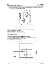
Mounting and connecting the device
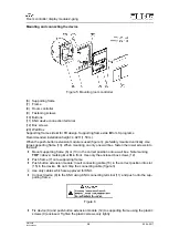
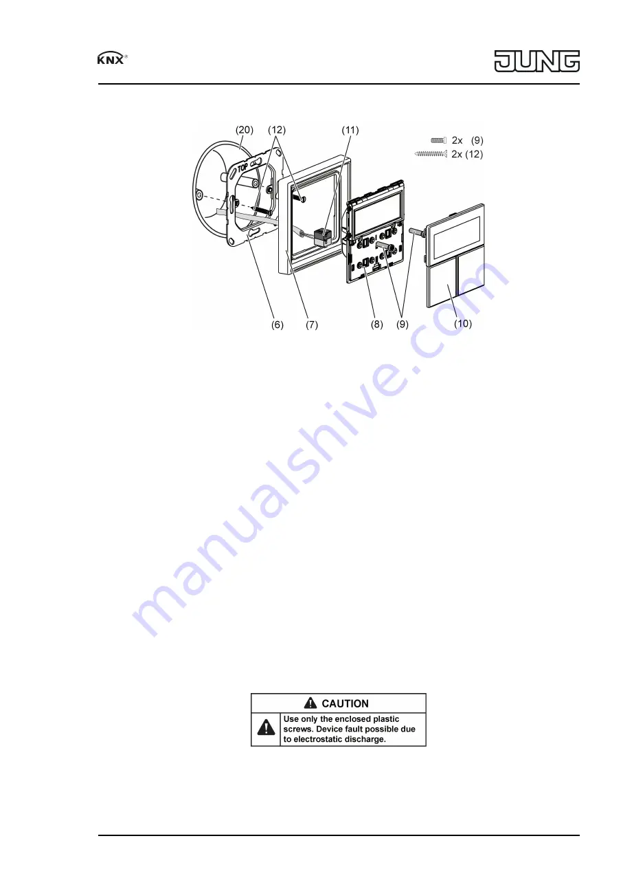
Figure 5: Mounting room controller
(6) Supporting frame
(7) Frame
(8) Room controller
(9) Fastening screws
(10) Buttons
(11) KNX device connection terminal
(12) Box screws
(20) Wall Box
Supporting frame side
A
for FD design. Supporting frame side
B
for LS programs.
Recommended installation height: 4.92 ft (1.50 m).
When the pushbutton extension module is used (figure 3): preferably mounted vertically. Use
large supporting frame (13). When mounting on only one wall box, fasten the lower screws into
the wall.
o
Mount supporting frame (6) or (13) in the correct position onto a wall box. Note marking
TOP
= above; marking
A
or
B
in front. Use only the enclosed box screws (12).
o
Push frame (7) onto supporting frame.
o
Pushbutton extension module: Insert connecting cable (16) in the correct position into slot
(15) in the device. Do not crimp the connecting cable (figure 3).
i
Use only cables which are approved for KNX.
o
Connect device (8) to the KNX using KNX connecting terminal (11) and push onto the sup
porting frame.
Figure 6
o
Fix device (8) and pushbutton extension module (12) to supporting frame using the plastic
screws (9) enclosed. Tighten the plastic screws only lightly.
5/8
Room controller display module 2-gang
82574805
J0082574805
29.06.2017

