background image

EN

46


Operating Manual: RWM200 - Smoke Alarm Device

5  Installation

The device is held by a magnetic carrier at 

the installation location.

The magnetic carrier can be mounted by 

gluing or drilling.

It is imperative to observe the instruc-

tions in this manual and the general safety 

instructions in order to prevent injuries 

caused by incorrect installation.

CAUTION

Possible property damage!

Using other fastening material (not 

enclosed) or wrong conditions at the 

installation location can cause the 

device to fall down.


f

Use only the supplied mounting 

material (adhesive pad or  

screws /dowels).


f

Ensure that the mounting location is 

strong enough, solid, dry, free from 

grease, dust and loose paint etc.


f

Note that the magnetic carrier 

magnetically attracts only from 

one side.

4.4  Rooms with a platform or gallery

0,5

1/2

0,5

0,5

>16 m

² 

/


>2 m 

1/2

Abb. 14  Rooms with a platform or gallery

Allowed
Not allowed

Note the following for rooms with plat-

forms or galleries (area greater than  

16 m

2

, at least 2 m long and wide):


f

Mount additional device under the 

platform / gallery.

Summary of Contents for RWM200

Page 1: ...RWM200 Rauchwarnmelder Smoke Alarm Device Betriebsanleitung Operating Manual...

Page 2: ...tones 57 EN DE Inhaltsverzeichnis 1 Hinweise zur Betriebsanleitung 3 2 Sicherheitshinweise 10 3 bersicht 14 4 Standortauswahl 16 5 Montage 22 6 Inbetriebnahme 25 7 St r und Fehlermeldungen 26 8 Insta...

Page 3: ...en soll Gefahren und Ausfallzeiten und ggf einen Verlust von Gew hrleistungsanspr chen vermeiden Die Betriebsanleitung muss zwingend ge lesen und verstanden werden F r eine bessere Lesbarkeit wird der...

Page 4: ...ige und unabh ngige Kontrollen auf unver nderte Einhaltung der gesetzlichen und normativenVorgaben berwacht Die Leistungser kl r ung f r ei n e n R a u c h w a r n m e l d e r RWM200 mit Q Label ist u...

Page 5: ...autorisierten H ndler erworben wurde f r die Dauer von 12 Jahren ab dem Kaufdatum unter bestimmungsgem en Einsatz und Wartungsbedingungen ein m ngelfreies Ger t Dabei erstreckt sich die beschr nk te...

Page 6: ...icht auf eine Fehlfunktion des Ger tes hin sondern zeigen lediglich einen Mangel an Pflege Reinigung und Wartung an Physische mechanische Besch digung Wenn das Ger t besch digt wurde z B das Geh use a...

Page 7: ...n Sofern es vorgekommen ist dass das Ger t und insbesondere dessen Elek tro nik durch Feuchtigkeit jedwelcher Art besch digt wurde ist damit der Verlust jeden Garantie Anspruches verbunden Unter Feuch...

Page 8: ...rst ren Sie nicht diese Siegelmarken da sonst etwaige Gew hrleistungs und oder Garantie sowie Produkthaftungsanspr che entfallen Ein Austausch des Insektenschutzgitters ist ausschlie lich durch eine z...

Page 9: ...e Rechte beschr nken sich auf die Re pa ratur oder den Ersatz dieses Produktes im Lieferzustand Die ALBRECHT JUNG GMBH CO KG bernimmt keine Haftung f r jegliche spezielle beil ufig entstandene oder Fo...

Page 10: ...er t d rfen Sie nur f r folgende Zwecke verwenden Raucherfassung und Hitzewarnung in pri vaten Haushalten und bewohnten Immobilien Rauchwarnmelder im Innenraum Einsatz in bewohnbaren Freizeit fahrzeug...

Page 11: ...recht zeitig reagieren insbesondere die brand beaufschlagten R ume sofort verlassen und die Feuerwehr alarmieren k nnen Rauchwarnmelder verhindern we der die Entstehung von Br nden noch bek mpfen sie...

Page 12: ...ter Sonneneinstrahlung und berm iger W rme Besch digung der Batterie Staub und Feinstaub Spinnen und Insektenbefall Fett Nikotin und Lackd mpfen Anstrichen z B Wandfarbe Klebstoffen Schmutz jeglicher...

Page 13: ...intr chtigt oder verhindert werden Es kann kein zuverl s siger Alarm ausgel st werden f f Dekorieren Sie ausschlie lich die Pr f Stopp Taste Abdeckung des Rauchwarnmelders und halten Sie die Raucheinl...

Page 14: ...erungssicherung 2 Aktivierungstaste 3 Magnettr ger 4 Raucheinlasslamellen 5 Pr f Stopp Taste Abdeckung Rauchwarnmelder Splint Aktivierungssicherung Der Splint Aktivierungssicherung dient w hrend desTr...

Page 15: ...n das Innere des Ger tes und kann von Sensoren erfasst werden Pr f Stopp Taste Abdeckung Rauchwarnmelder Mit der Pr f Stopp Taste Abdeckung Rauchwarnmelder kann ein Selbsttest ausgel st werden Die Pr...

Page 16: ...Standortauswahl Mindestausstattung optimale Ausstattung unterVorbehalt wegen Wasserdampf nicht montieren Dachboden G stezimmer B ro Schlafzimmer Kinderzimmer Wohnzimmer K che Heizung Werkraum Schlafz...

Page 17: ...Grund der hohen Entwicklung von Wasser dampf von der Ausstattung mit Rauchwarnmeldern ausgenommen Ausnahme Badezimmer mit Waschmaschinen und Schr nken 4 1 berwachungsfl che Setzen Sie ein Ger t ein w...

Page 18: ...0 5 m zu umlie genden W nden M belst cken und Lampen einhalten Zuggef hrdete Umgebung Damit aufkommender Rauch den Rauchwarnmelder erreichen kann d r fen am Installationsort keine stark zugbil denden...

Page 19: ...ten einhalten Schmale R ume oder Flure 1 m breit Beachten Sie zus tzlich Folgendes bei der Standortauswahl in schmalen R umen oder Fluren die weniger als 1 m breit sind f f Kapitel R ume mit geraden R...

Page 20: ...ume mit schr gen und waagerechten Raumdecken 1 00 20 1 2 1 2 Abb 5 gerade Montagefl che mindestens 1 m lang und 1 m breit erlaubt nicht erlaubt Beachten Sie Folgendes wenn die gerade Montagefl che mi...

Page 21: ...mit schr gen Raum decken Neigungswinkel 20 auf Seite 19 beachten 4 4 R ume mit Podest oder Galerie 0 5 1 2 0 5 0 5 16 m 2 m 1 2 Abb 7 R ume mit Podest oder Galerie erlaubt nicht erlaubt Beachten Sie F...

Page 22: ...t herunterfallen f f Verwenden Sie ausschlie lich das mitgelieferte Befestigungsmaterial Klebepad oder Schrauben D bel f f Stellen Sie sicher dass der Mon tageort ausreichend tragf hig fest trocken f...

Page 23: ...Verbindung zwi schen Ger t und Magnettr ger nach vfdb 14 01 Q herzustellen m s sen Sie mit der zus tzlich mitgelie ferten Klebefolie das Ger t auf dem Magnettr ger befestigen VORSICHT M gliche Sachsc...

Page 24: ...t ist auf dem Magnettr ger montiert 5 2 Bohrmontage Als Alternative zur Klebemontage k n nen Sie den Magnettr ger auch an den Montageuntergrund anschrauben Auch bei der Bohrmontage muss das Klebepad...

Page 25: ...betriebnahme auf Seite 25 beachten 8 Ger t auf den Magnettr ger setzen 5 5 Magnettr ger ist montiert und das Ger t aufgesetzt 6 Inbetriebnahme Beachten Sie bei der Inbetriebnahme Folgendes 1 Splint se...

Page 26: ...cher Ton siehe Kapitel 12 Alarm und Hinweist ne auf Seite 57 Gehen Sie wie folgt vor 1 Pr f Stopp Taste dr cken um die Kontaminationsmeldung f r 24 Stun den zu deaktivieren 2 Ger t austauschen Das Ger...

Page 27: ...mittelbarer N he und hoher Konzentration einen Alarm aus Folgende Abhilfema nahmen k nnen Sie treffen f f Alarm stoppen siehe Kapitel Alarm Stopp auf Seite 25 f f auf eine ausreichende Bel ftung des M...

Page 28: ...vorsichtig reinigen z B mit einem Staubsauger und feuchtemTuch 8 1 Wartung In regelm igen Abst nden m ssen Sie Sicht und Funktionspr fungen durchf hren Sichtpr fung F hren Sie einmal im Monat eine Si...

Page 29: ...ElektroG nicht in den Hausm ll gelangen f Senden Sie das zu entsorgende Ger t an den Hersteller zur weite renVerwertung oder geben es bei Ihrem regionalen Entsorgungsunter nehmen ab f Beachten Sie da...

Page 30: ...al is read and understood For a better readability the RWM200 smoke alarm device is hereinafter referred to as smoke alarm device or device 1 1 Scope of operating manual The operating instructions app...

Page 31: ...n of performance for smoke detectors RWM200 with Q la bel is available at the following reference number at the manufacturer RWM200 1 4 Safekeeping of the instruction manual The instruction manual is...

Page 32: ...xtend to the reserve power supply to the electronics of the device whereas the material workman ship errors are exempt from this restriction The limited warranty is not transfera ble and does not appl...

Page 33: ...ed Paint and similar substances on the surface of the device and within the housing measurement system of the device shall be deemed contamination Decoration painting limited to the release testing st...

Page 34: ...o high temperatures and fumes in a fire Damage to the device as a result of frost cold as well as heat damage shall not be covered by the warranty Excessive load on the battery Excessive load on the b...

Page 35: ...ed warranty shall not apply the liability of ALBRECHT JUNG GMBH CO KG shall be limited to the purchase price of the device sufficient technical capabilities to determine when submitting a warranty cla...

Page 36: ...tial real estate Smoke alarm device indoors Use in leisure accommodation vehicles e g caravans Note the following when using the smoke alarm device f f Use the device only as intended and in a technic...

Page 37: ...ke alarms do not directly alert the fire brigade or other emergency service Smoke alarm devices are not used to prevent fire damage and they cannot in fact prevent it especially when no one is present...

Page 38: ...d Immersion in water Immersion in water can cause damage to the device f f Do not immerse the device in water Open the device The device is a closed system Any tamper ing with the device in addition t...

Page 39: ...evice and keep the smoke intake lamella free Renovation work During renovation construction and grinding work malfunction or damage to the device may occur due to the development of dust f f Remove th...

Page 40: ...he device Smoke intake lamella Through the smoke intake lamella fire smoke reaches the interior of the device and can be detected by sensors Testing stop button smoke alarm device cover A self test ca...

Page 41: ...mal equipment Conditional Do not install due to steam Attic Guest room Office Bedroom Children s bedroom Livingroom Kitchen Heating Workroom Bedroom Bath room Kitchen Corridor Livingroom Children s Be...

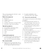
Page 42: ...d from the in stallation of smoke alarm devices due to the high development of steam Exception bathrooms with washing machines and cabinets 4 1 Area to be monitored Use a device if at least one of the...

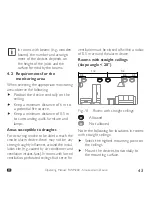
Page 43: ...e and lamps Areas susceptible to draughts For occurring smoke to be able to reach the smoke alarm device there may not be any strong draughty influences around the instal lation site e g caused by air...

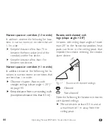
Page 44: ...in narrow rooms or corridors that are less than 1 m wide f f Observe chapter Rooms with straight ceilings slope angle 20 on page 43 f f Keep distance from surrounding walls exception distance less tha...

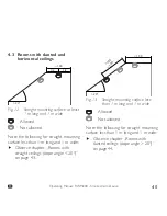
Page 45: ...following for straight mounting surface less than 1 m long and 1 m wide f f Observe chapter Rooms with straight ceilings slope angle 20 on page 43 1 00 0 50 1 00 20 Fig 13 Straight mounting surface le...

Page 46: ...r wrong conditions at the installation location can cause the device to fall down f f Use only the supplied mounting material adhesive pad or screws dowels f f Ensure that the mounting location is str...

Page 47: ...ic carrier 2 Remove the protective film from the adhesive pad on the magnetic carrier Press firmly magnetic carrier for about 10 seconds at the mounting position 3 Taking the device into operation f f...

Page 48: ...ier f f Observe chapter Adhesive mounting according to EN 14604 2005 AC 2008 on page 47 2 Take the device into operation f f Observe chapter 6 Putting into operation on page 50 3 Attach additional adh...

Page 49: ...f Tighten the screw only so deep that the magnetic carrier is not deformed or bulged 6 To ensure a safe hold of the device tighten the screw deep into the dowel so that it closes flush with the magne...

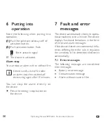
Page 50: ...ing again after 10 minutes You can stop the alarm directly on the device f f Press the testing stop button on the device 7 Fault and error messages The device automatically checks its opera tional rea...

Page 51: ...residential areas that are promoted by textiles e g carpets clothing blankets and pillows Pollen construction grinding or fine dust DANGER Danger from malfunction In the event of a battery error mess...

Page 52: ...m see chapter Alarm stop on page 50 f f Ensure adequate ventilation of the installation location f f Handle the device with care and clean it regularly e g with a vacuum cleaner f f Inform neighbours...

Page 53: ...nsure that the devices are operational you must check the function of each de vice using a test tone f f If no test tone sounds you must replace the device Test tone device Trigger a test tone at leas...

Page 54: ...irective this product should never be placed in do mestic waste f Return the appliance to be discard ed to the manufacturer for further utilisation or hand it over to your local waste disposal company...

Page 55: ...Up to 6 m room height Batterie Battery 3 0V Lithium 2 3 A fest eingel tet 3 0 V lithium 2 3 A firmly soldered Batterielebensdauer Battery life 12 Jahre 12 years Akustischer Alarm Audible alarm 85 dB O...

Page 56: ...enspeicher mit Exportfunktion Readable data storage with Export function Vorhanden Available Montage Installation Acrylatschaumklebepad f r Schraub und Klebemontage Acrylate foam adhesive pad for scre...

Page 57: ...ion Ursache Cause Lautst rke Noise level Intervall Interval Hinweiston Inbetriebnahme Start up alert tone Aktivierungston Activation sound Hinweiston Instandhaltung Maintenance alert tone Pr fton Test...

Page 58: ...EN Hinweist ne St r und Fehlermeldungen Alert tones for error messages Batteriest rungs meldung Batter y er ror message Kontaminations meldung Contamination message 90 Sekunden Seconds 90 Sekunden Se...

Page 59: ...g stop button D i e H i n we i s t n e B a t t e r i e s t r u n g s m e l d u n g u n d Kontaminationsmeldung k nnen Sie durch Dr cken der Pr f Stopp Taste f r 24 Stunden vor bergehend deaktivieren D...

Page 60: ...1701_BDA_RWM200_V02 Stand der Betriebsanleitung 2016 10 Revision of the brochure 2016 10 Impressum ALBRECHT JUNG GMBH CO KG Volmestr 1 58579 Schalksm hle GERMANY kundencenter jung de www jung de Tel 4...

Reviews: