background image

040

1.G

B

E 6

4.2

Driving, steering, braking

f

Increased attention has to be paid during driving and steering the truck, especially if
movements outside of the truck contour are to be performed.
It is not admissible to stay on the vehicle during driving.

Driving with load lifting devices or loads lifted higher than the ground clearance di-
stance is only permitted when the load is to be picked up or to be lowered to the
ground. From a certain type dependant lift height, the drive speed is automatically re-
duced during lifting and increased again during lowering.

EMERGENCY STOP

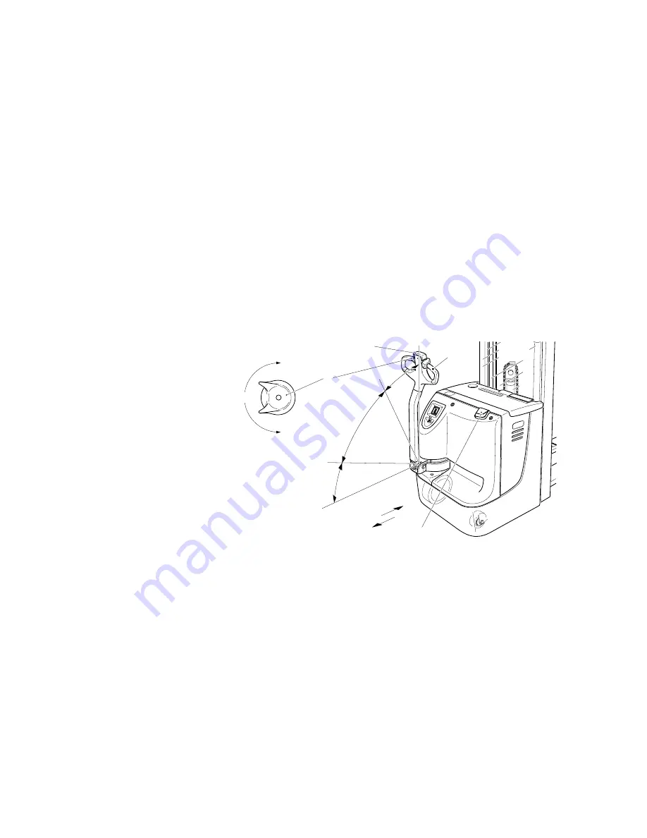
– Push master switch (1) down.

All electric functions are switched off. The truck is compulsory braked.

Emergency stop

When the control shaft (4) is released, the truck is compulsory braked (emergency
stop) - the control shaft (4) automatically swivels into the upper braking range (B).

f

If the control shaft (4) swivels only slowly into the braking position, it is required to per-
form troubleshooting measures. For example, the return spring must be exchanged!

Driving 

f

Do not drive the truck unless the hoods are closed and locked in the stipulated man-
ner. When driving through swinging doors, etc., make sure that the doors do not trig-
ger the collision-guard button (9). 

– Commissioning the truck (see section 3).
– Push the control shaft (4) into the driving range (F) and set the driving switch (8) to

the desired driving direction (V or R).

The truck starts to drive into the selected direction.

A

The driving speed can be continuously regulated with the driving switch (8).

0

R

R

V

B

F

B

V

4

8

9

1

Summary of Contents for EJC 14

Page 1: ...Operating instructions 10004249 EJC EJC Z 14 16 G 06 98 01 06...

Page 2: ...explanations are indicated by the following graphics f Used before safety instructions which must be observed to avoid danger to personnel m Used before notices which must be observed to avoid materi...

Page 3: ...0108 GB...

Page 4: ...Service No B 9 C Transportation and commissioning 1 Transportation by crane C 1 2 First commissioning C 2 3 Moving the truck without own drive C 3 D Battery Servicing recharging replacement 1 Safety r...

Page 5: ...d inspection F 3 4 Maintenance checklist F 4 5 Lubrication schedule F 6 5 1 Fuels coolants and lubricants F 7 6 Notes on maintenance F 8 6 1 Preparation of the truck for servicing and maintenance oper...

Page 6: ...f or on whose behalf it is used In special cases e g leasing or renting the user is conside red the person who in accordance with existing contractual agreements between the owner and the user of the...

Page 7: ...0600 GB A 2...

Page 8: ...rting palleted goods on level ground Either open ground pallets or trolleys can be picked up A wheel arm lifting device is available as an option extending the ground clearance during transports on un...

Page 9: ...ol shaft with control shaft head 4 t t Shunt driving button 5 t t Driving regulator 6 t t Collision guard button 7 t t Hoist frame 8 t t Protective pane 9 t t Battery hood 10 t t Master switch emergen...

Page 10: ...100 mm h3 Lifting height depending on mast short long 2500 4300 2500 5350 2400 4200 2400 5250 mm h4 height with mast protruded depending on mast type 7 short long 2981 4781 2981 5831 2931 4731 2931 5...

Page 11: ...with mast protruded 7 depending on mast type short long 2981 4781 2981 5831 2931 4731 2931 5781 mm h5 Free lifting capacity double lifting de vice depending on mast type 4 8 1219 2119 1169 2069 mm h13...

Page 12: ...B 5 0401 GB h4 h3 h1 l2 l1 l c y Q h5 h2 h31 h13 b5 Ast W a B m2...

Page 13: ...for electromagnetic emission and interference immunity as well as testing of static electricity dischar ge according to prEN 12895 and the references to other standards contained therein A Electrical...

Page 14: ...load lifting device 23 Prohibition sign Do not put your hands through the hoist frame 24 UVV control label 25 Identification label battery 26 Warning sign Caution Low voltage electronics 18 17 22 26...

Page 15: ...shaped markings on the inner mast 40 and outer mast 41 show the driver when he has reached the lifting height limits that is defined on the load capacity label 18 Item Designation Item Designation 27...

Page 16: ...a label 17 indicating the permissible assignment to wheel arm lifting device and main lifting device 4 4 Label Order Inventory Service No A This label contains the Full Service No and is only handed o...

Page 17: ...0401 GB B 10...

Page 18: ...ruck with the help of hoisting gear Trucks that are provided a with wheel arm lifting device have two more hoisting points 2 for loading Park the truck and render it safe refer to chapter E Attach the...

Page 19: ...t be performed Check whether the equipment is complete and in perfect condition If required mount the battery make sure not to damage the battery cable see chapter D A At trucks with an optionally bui...

Page 20: ...ove the key Secure the truck against rolling away Open and remove front hood see chapter F Turn the screws 3 anticlockwise until you reach the limit stop The solenoid brake is triggered The truck can...

Page 21: ...0401 GB C 4...

Page 22: ...cable shoes must be clean lightly greased with pole grease and must be securely tightened Batteries with bare terminal posts must be covered using a non skid insulating mat Disposal of the battery Ba...

Page 23: ...table shows the standard battery combinations and battery capacities Depending on the battery type also high performance or maintenance free batteries can be used 3 Open battery hood Park the truck a...

Page 24: ...Expose the battery refer to section 3 f During the recharging operation the tops of the battery cells must be exposed to en sure adequate ventilation Metal objects must not be placed on the battery P...

Page 25: ...recharged Select charging curve in the integrated battery charger Use switch 7 at the battery charger to adjust the charging curves to the appropriate battery according to the following table m The p...

Page 26: ...The power plug 8 of the battery charger can be found in the battery compartment Expose the battery refer to section 3 Remove insulation mat from battery if necessary Pull out master switch 2 position...

Page 27: ...the battery LED display Fill up charge The fill up charge begins automatically after the recharge procedure has ended Partial recharging The battery charger is designed in such a way that it automatic...

Page 28: ...Before commissioning the truck the battery hood must be properly closed A When changing the battery with the aid of a lifting gear ensure that the lifting gear is of adequate capacity the battery wei...

Page 29: ...battery cable of the truck must be laterally led outside While removing the bat tery make sure that the cable is not squeezed Attach hoisting gear to the hoisting ears 9 Lift out the battery The re as...

Page 30: ...ery 11 from the truck onto the battery trolley battery change station f Be careful not to place your fingers between partition wall of the truck and the battery Heed the operating instructions of the...

Page 31: ...is reached a CAUTION icon 15 is in dicated Recharging the battery is recommen ded When a remaining battery capacity of 20 for standard batteries 40 for maintenance free batteries is reached the CAUTI...

Page 32: ...uck or on the attach ments must immediately be brought to the notice of the person in charge fork lift trucks that cannot be safely operated e g due to worn tyres or defective brakes must not be used...

Page 33: ...be mo ved with reduced speed shunt dri ving 6 Button wheel arms lowering t Wheel arms are lowered with constant speed 7 Button wheel arms lifting t Wheel arms are lifted with constant speed 8 Driving...

Page 34: ...E 3 0401 GB 2 1 3 4 5 8 8 10 11 12 9 13 14 15 16 7 6...

Page 35: ...of the whole truck especially tyres and load carrying devices Visual inspection of battery fixing and cable connections Starting up the truck Pull out master switch 1 Put key into the key switch 2 an...

Page 36: ...always be carried at that end of the truck facing uphill U turns cutting obliquely over slopes or inclines and parking of the fork lift truck on slopes or inclines is not permitted Inclines must only...

Page 37: ...aked Emergency stop When the control shaft 4 is released the truck is compulsory braked emergency stop the control shaft 4 automatically swivels into the upper braking range B f If the control shaft 4...

Page 38: ...he service brake and to select the desired driving speed and direction f If the roll off brake was deactivated by the service only service brake and counterflow brake are available Steering Swivelling...

Page 39: ...aft 4 Swivel control shaft 4 upwards or downwards into one of the braking ranges B The drive motor is mechanically braked A When the control shaft 4 is released it swivels into the upper braking range...

Page 40: ...capacity is realised without changing the overall height with the help of a short free lifting cylinder which is centrally arran ged From a specific lifting height onwards depending on the design the...

Page 41: ...l arms 6 but ton Keep the button pressed until the desired lowering height has been rea ched Emergency lowering system f The emergency lowering system may only be used if there are no persons within t...

Page 42: ...service personnel Fault Possible cause Remedy Truck does not move Battery connector not connected Check the battery connector and reconnect it if necessary Master switch EMERGENCY STOP pressed Releas...

Page 43: ...0401 GB E 12...

Page 44: ...ians trained especially for these assignments We thus recommend signing a maintenance contract with the relevant service location of the manufacturer Lifting and jacking up When a fork lift truck is t...

Page 45: ...he quality of the tyres greatly affects the stability and the driving behaviour of the fork lift truck The factory mounted tyres must only be replaced by original spa re parts of the manufacturer sinc...

Page 46: ...iple shift operation the servicing intervals must be shor tened accordingly The following servicing checklist indicates the operations to be performed and the re spective intervals to be observed The...

Page 47: ...st frame 6 1 Visual check of rollers slide pieces and stops k t 6 2 Check fork tines and fork carrier for wear and damage k t 6 3 Check secure attachment of hoist frame t 6 4 Check lift chains and cha...

Page 48: ...wear of collector k t Battery 11 1 Check acid density acid level and cell voltage k t 11 2 Check the terminals for secure attachment and apply pole grease k t 11 3 Clean battery connections check for...

Page 49: ...nipple Filler neck for hydraulic oil b Filler neck Gear oil a Drain plug Gear oil 1 Mixing proportion for application in cold storage depots 1 1 2 Tandem load wheel 3 Filling level see Check hydraulic...

Page 50: ...qualitiies resp except if mi xing is expressively prescribed in these operating instructions Avoid spilling Spilt liquid must be removed immediately using a suitable binding agent and the mixture of...

Page 51: ...rised truck ope ration f When work has to be performed under the jacked up truck suitable measures must be taken to prevent any dropping tilting or slipping of the truck When lifting the truck the ins...

Page 52: ...on 6 2 Loosen 2 x screws 5 using the key 2 Remove carefully the wheel cover 4 Check gear oil level oil level must reach the filler neck see section 5 If required top up with gear oil with the required...

Page 53: ...ood see section 6 3 Referring to the table check all fuses for correct rating and replace where required Item Description Protection of Value 8 F1 Total control fuse 10 A 9 1F1 Drive motor in parallel...

Page 54: ...more than 6 months additional mea sures must be discussed with the Service Department of the manufacturer 7 1 Operations to be performed prior to decommissioning Thoroughly clean the fork lift truck...

Page 55: ...ked by a qualified inspector The inspector must assess the condition of the truck from a standpoint purely concerned with safety aspects uninfluenced by any company or economic circumstances The insp...

Reviews: