background image

2

Displays and Controls

14, 64

60

18

17

10

13, 62

12

58

57

59

56

55

60

61

58

57

56

55

60

59

60

61

65

63

61

04.19 en-GB

Summary of Contents for EJD 220

Page 1: ...EJD 220 01 10 Operating instructions 51132781 04 19 en GB EJD 220...

Page 2: ...2...

Page 3: ...JD 220 On behalf of Date EU DECLARATION OF CONFORMITY The undersigned hereby declare that the powered truck described in detail complies with the current versions of European Directives 2006 42 EG Mac...

Page 4: ...4 04 19 en GB...

Page 5: ...lar features of the truck should therefore be assumed from the present operating instructions Safety notices and text mark ups Safety instructions and important explanations are indicated by the follo...

Page 6: ...ht Copyright of these operating instructions remains with JUNGHEINRICH AG Jungheinrich Aktiengesellschaft Friedrich Ebert Damm 129 22047 Hamburg Germany Tel 49 0 40 6948 0 www jungheinrich com 6 04 19...

Page 7: ...eights 26 4 4 Tyre type 26 4 5 EN norms 27 4 6 Specifications according to RED guideline Radio Equipment Directive for radio units 28 4 7 Conditions of use 28 4 8 Electrical requirements 28 4 9 Safety...

Page 8: ...eshooting 95 5 1 Truck does not start 96 5 2 Load cannot be lifted 98 6 Operating the truck without its own drive system 99 6 1 Release and activate the drive wheel brake 99 7 Load handler emergency l...

Page 9: ...175 4 7 Check the gear oil level 176 4 8 Check wheel attachment and wear 177 4 9 Checking electrical fuses 179 4 10 Restoring the truck to service after maintenance and repairs 180 5 Decommissioning t...

Page 10: ...10 04 19 en GB...

Page 11: ...ngheinrich battery models If using another brand refer to the manufacturer s operating instructions 1 0506 GB Appendix JH Traction Battery Operating Instructions Z These operating instructions apply o...

Page 12: ...0506 GB 2 0506 GB 2...

Page 13: ...e indicated on the capacity plate and must not be exceeded The load must rest on the load handler or be lifted by an attachment approved by the manufacturer The load must be fully raised see page 85 L...

Page 14: ...oss or at an angle on inclines Travel with the load facing uphill Operation in partially public traffic WARNING Use under extreme conditions Using the truck under extreme conditions can result in malf...

Page 15: ...n in Cold Stores with Cold Store Equipment o In addition to the permissible operating conditions in industrial and commercial environments the truck remains primarily in cold stores The truck should o...

Page 16: ...ed Furthermore accident prevention regulations safety regulations and operating servicing and repair guidelines must be followed The operating company must ensure that all users have read and understo...

Page 17: ...ation two pallets can be stacked on top of each other Open bottom pallets or roll cages can be lifted 1 1 Truck models and rated capacity The rated capacity depends on the model The rated capacity can...

Page 18: ...16 04 19 en GB...

Page 19: ...Travel direction definition The following determinations have been made for travel direction specification 1 2 3 4 Item Travel direction 1 Left 2 Drive direction 3 Load direction 4 Right 17 04 19 en G...

Page 20: ...3 Assemblies and Functional Description 3 1 Assembly Overview 15 5 7 19 18 11 16 17 6 14 13 12 10 8 9 15 18 04 19 en GB...

Page 21: ...eypad 7 t Battery panel o Transponder reader 8 t Collision safety switch 15 t Support wheel 9 t Travel switch 16 t Drive wheel 10 t Slow travel button 17 o On board battery charger 11 t Load handler 1...

Page 22: ...s The mast protection pane or grille o protect the operator from moving mast parts and the load Emergency stop safety concept The emergency stop is activated by the traction controller Each time the t...

Page 23: ...braking with energy regeneration The driver can choose from 3 travel programs depending on the load and the environment from high performance to energy saving Tiller The driver steers with an ergonom...

Page 24: ...d mast height h4 increases according to the load backrest mounted on the load handler WARNING Risk of injury from falling loads Low or small item loads moved above the mast protection pane or grille o...

Page 25: ...0 kg Capacity for mast lift 1 1000 kg Capacity for support arm lift 2000 kg D Load centre distance 600 mm Travel speed with without rated load 6 0 6 0 km h Lift speed with without rated load 0 14 0 25...

Page 26: ...4 2 Dimensions h1 h3 h4 D b1 h14 b1 b10 m2 24 04 19 en GB...

Page 27: ...1190 mm b10 Track width front 508 mm b11 Track width rear 385 mm m2 Ground clearance centre wheelbase 20 mm Ast Aisle width with pallet 1000x12000 traverse 2 4 2233 mm Ast Aisle width with pallet 800...

Page 28: ...20 1825 1160 1872 kg Axle loading unladen front rear battery 665 280 732 300 kg Battery weight 220 288 kg 4 4 Tyre type Tyre size drive 230 x 65 mm Load section tyre size single tandem 85 x 95 85 x 75...

Page 29: ...resistance as well as the static electricity discharge test in accordance with EN 12895 as well as the standardised instructions contained therein Z No changes to electric or electronic components or...

Page 30: ...C to 40 C see page 13 with cold store equipment operating at 28 C to 25 C see page 13 Z Special equipment and authorisation are required if the truck is to be used continually in conditions of extrem...

Page 31: ...oints and Data Plates Z Warnings and notices such as capacity charts strap points and data plates must be legible at all times Replace if necessary 5 1 Indication Points 20 24 26 22 23 29 25 28 27 21...

Page 32: ...ith ZZ mast in the middle 22 Capacity plate 23 Capacity plate for stacking transport and double deck operations 24 Prohibition plate Do not reach through the mast 25 Serial number 26 Prohibition plate...

Page 33: ...Item Description 31 Type 37 Year of manufacture 32 Serial number 38 Load centre distance mm 33 Rated capacity kg 39 Nominal power 34 Battery voltage V 40 Min max battery weight kg 35 Net weight withou...

Page 34: ...g for a given load centre distance D in mm and corresponding lift height H in mm for the truck when raising a load Example of how to calculate the maximum capacity The maximum capacity is Q1 at a load...

Page 35: ...e distances of 500 mm 600 mm and 700 mm The distances d1 and d2 depicted in the illustration between the load handler and the actual centre of gravity G of the load must be smaller or equal to the loa...

Page 36: ...entire volume the load centre distance is in the middle i e half the length half the height and half the width of the load Load centre distance of the load handler The capacity plate specifies valid...

Page 37: ...f a truck when lifting lowering and transporting loads with large surface areas Light loads must be especially secured when they are subjected to wind forces This will prevent the load from sliding or...

Page 38: ...A B C A Stacking operations storing and retrieving loads Maximum capacity for high level lifting mast lift is 1000 kg B Transport operations Maximum capacity when transporting loads horizontally 2000...

Page 39: ...he truck to crash when being loaded by crane Prevent the truck from hitting other objects during lifting and avoid uncontrolled movements If necessary secure the truck with guide ropes uThe truck may...

Page 40: ...nts Park the truck securely see page 70 Remove any mast guards Tools and Material Required Lifting gear Crane lifting gear Procedure Secure the lifting slings to the strap points 21 The truck can now...

Page 41: ...lied uThe truck must be securely fastened when transported on a lorry or a trailer uThe lorry or trailer must have fastening rings uUse wedges to prevent the truck from moving uUse only fastening belt...

Page 42: ...n now be started see page 67 NOTICE Do not lift loads if the truck is operated via a tow lead with an external battery NOTICE Cold store trucks uTrucks designed for use in cold stores have a cold stor...

Page 43: ...nt must be available CAUTION The use of unsuitable fire protection equipment can result in scalding Extinguishing fires with water can cause a reaction with the battery acid This can result in scaldin...

Page 44: ...by Jungheinrich for the truck can be hazardous The design weight and dimensions of the battery have a considerable effect on the operational safety of the truck in particular its stability and capaci...

Page 45: ...12X628 24 V battery 2 PzQ 276 204 624X212X628 24 V battery 3 PzV 300 273 624X284X628 24 V battery XFC 316 273 624X284X628 24 V battery 3 PzV 330 273 624X284X628 24 V battery 2 PzS 375 273 624X284X628...

Page 46: ...akes are not working place wedges underneath the wheels of the truck to prevent it from moving CAUTION A closing battery panel can pose a trapping hazard If the battery cover is not opened fully it ca...

Page 47: ...isible signs of damage uVentilate the room in which the truck is being charged uThe battery cover must be open and the battery cell surfaces must be exposed during charging to ensure adequate ventilat...

Page 48: ...rating instructions The battery is charging 46 47 Completing battery charging restoring the truck to operation NOTICE If charging has been interrupted the full battery capacity will not be available R...

Page 49: ...e a short circuit or electric shock uDo not trap the mains cable when closing the battery panel uReport any defects immediately to your supervisor uNotify the customer service department uMark the def...

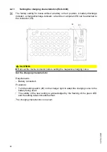
Page 50: ...49 48 49 CAUTION uRemove the mains connector before setting the respective charging curve Set the charging characteristic Requirements Battery connected Procedure Turn the setting switch 48 on the cha...

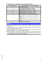
Page 51: ...l battery PzS with pulse characteristic 200 414 Ah 6 Jungheinrich 100 300 Ah NOTICE uAll other switch positions 48 block the battery charger and the battery is not charged uSet characteristic curve 1...

Page 52: ...g the charging characteristics ELH 2415 2425 2435 The charging characteristics are set via parameter 1388 of the truck software The setting is made by the manufacturer s customer service department 50...

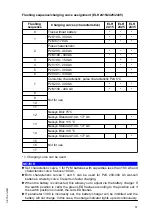
Page 53: ...C Nexsys Standard 140 177 Ah 15 Not for use 16 17 Charging curve can be used NOTICE uSet characteristic curve 1 for PzM batteries with capacities less than 180 Ah and characteristic curve 5 above 180...

Page 54: ...se the battery see page 44 Correct charging program set on charger Procedure Remove any insulating mats from the battery The battery connector must remain plugged Attach the mains connector 51 to a ma...

Page 55: ...e compartment 50 If applicable place the existing insulating mats back over the battery Close the battery panel securely The truck is now ready for operation CAUTION Damaged mains cables can be hazard...

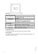
Page 56: ...teristic curve set Red LED fault Lit Overtemperature Charging is interrupted Flashes slowly Safety charging time exceeded Charging is cancelled Mains must be disconnected for charging to restart Rapid...

Page 57: ...ies with insulated cells and terminal connectors uPark the truck on a level surface to prevent the battery from sliding out uMake sure the crane slings have sufficient capacity to replace the battery...

Page 58: ...s now been removed 53 54 Battery installation NOTICE uMake sure the battery is installed and connected correctly uPlace the battery cable on the tray so that it cannot be severed when the battery is i...

Page 59: ...53 54 57 04 19 en GB...

Page 60: ...58 04 19 en GB...

Page 61: ...structions Safety shoes must be worn on pedestrian operated trucks Unauthorised use of truck The operator is responsible for the truck during the time it is in use The operator must prevent unauthoris...

Page 62: ...hazardous area stop the truck immediately Safety devices warning signs and warning instructions Safety devices warning signs see page 29 and warning instructions in the present operating instructions...

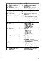
Page 63: ...2 Displays and Controls 14 64 60 18 17 10 13 62 12 58 57 59 56 55 60 61 58 57 56 55 60 59 60 61 65 63 61 04 19 en GB...

Page 64: ...s the key switch Enteri ng the appro priate code activa tes the truck Travel progr am select ion Code settin g Settin g of para meter s 17 On board battery charger with safety circuit o For charging...

Page 65: ...switched off until the travel switch is moved to the neutral position 62 CanDis o Display instrument for Battery charge status Service hours Warning messages Parameter setting 63 Display unit 2 inch...

Page 66: ...codes Transponder reader o Replaces the key switch Provided only as a supplement to the display unit Activates the truck via a card transponder ISM o Replaces the key switch Activates the truck via a...

Page 67: ...djustment is not made the battery may become damaged due to deep discharge NOTICE Full discharge can damage the battery Self discharge can cause the battery to fully discharge Full discharge shortens...

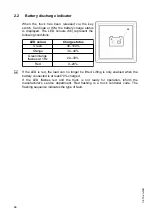
Page 68: ...s Green 40 100 Orange 30 40 Green orange flashes at 1 Hz 20 30 Red 0 20 Z If the LED is red the load can no longer be lifted Lifting is only enabled when the battery connected is at least 70 charged I...

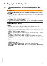
Page 69: ...ck for signs of damage and leaks Damaged hoses must be replaced immediately Check the battery attachment and wire connections for damage and make sure they are secure Check the battery connectors are...

Page 70: ...card or transponder in front of the ISM access module and depending on the setting press the green button on the ISM access module o Z The tiller 12 must be in the upper braking zone B If event messag...

Page 71: ...rvice until you have identified and rectified the fault Procedure Test warning indicators and safety equipment Test the emergency disconnect function by pressing the emergency disconnect switch The ma...

Page 72: ...handler raised uPark the truck on a level surface In special cases the truck may need to be secured with wedges uFully lower the load handler when leaving the truck uSelect a place to park where no o...

Page 73: ...ow speed when negotiating bends or narrow passageways when passing through swing doors and at blind spots The operator must always observe an adequate braking distance between the forklift truck and t...

Page 74: ...lifts with the load in front and must take up a position which does not allow it to come into contact with the walls of the lift shaft Persons riding in the lift with the forklift truck must only ent...

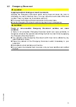
Page 75: ...es CAUTION Faulty or non accessible Emergency Disconnect switches can cause accidents A faulty or non accessible Emergency Disconnect switch can cause accidents In dangerous situations the operator ca...

Page 76: ...isconnect switch on in emergencies Releasing the Emergency Disconnect switch Procedure Pull the Emergency Disconnect switch 18 to unlock it All electrical functions are enabled and the truck is operat...

Page 77: ...sk of collision due to a defective tiller Operating the truck with a defective tiller can lead to collisions with persons or objects uIf the tiller returns to the brake position slowly or not at all t...

Page 78: ...direction 3 Travel in load direction Rotate the travel switch 9 slowly in the drive direction 2 Travel in drive direction Control the travel speed with the travel switch 9 The further the travel swit...

Page 79: ...speed when the load handler is fully loweredI When the load handler is fully lowered the truck can only travel at reduced speed The load handler must be raised in order to use the maximum available s...

Page 80: ...travel switch is released in time uAfter setting off in the opposite direction apply the travel switch gently or not at all uDo not perform any sudden steering operations uAlways face in the direction...

Page 81: ...e g in confined spaces elevators Switch on the slow travel function Procedure Press and hold down the slow travel button 10 Rotate the travel switch 9 in the required travel direction The brake is re...

Page 82: ...ing direction CAUTION uIn hazardous situations swing the tiller to the brake position or press the emergency disconnect switch 4 7 1 Braking with the service brake Procedure Move the tiller 12 up or d...

Page 83: ...el switch 9 to the opposite direction while travelling see page 78 The truck brakes regeneratively until it starts to move in the opposite direction 4 7 4 Parking brake Z The mechanical brake applies...

Page 84: ...ning prevent the truck from being used by unauthorised people uOnly carry loads that have been secured and positioned in accordance with regulations Use suitable precautions to prevent parts of the lo...

Page 85: ...u have reached the mechanical limit position of the load handler do not press the raise load handler button any longer Otherwise the hydraulic unit could suffer material damage Z The lifting lowering...

Page 86: ...usted via the travel of the button approx 8 mm Short switch stroke slow lower Long switch stroke fast lower The load handler is lowered 4 8 3 Raising the wheel arms Requirements Prepare the truck for...

Page 87: ...r uPreferably the load should be configured and picked up so that its centre distance lies within the load centre distance of the load handler d1 D and d2 D see area DD in the illustration uA load wit...

Page 88: ...ximum loads specified on the load diagram uNever stand underneath a raised load handler uDo not stand on the load handler uDo not lift other people on the load handler uInsert the load handler as far...

Page 89: ...eyond the load handler tips Raise the load handler until the desired height is reached see page 83 The load is being raised NOTICE Risk of material damage to the hydraulic unit When the mechanical sto...

Page 90: ...your travel speed to the conditions of the travel paths and the load you are transporting Travel at a constant speed Be prepared to brake at all times Brake gently in normal circumstances Only stop ab...

Page 91: ...and the load handler avoid setting the load down abruptly Lower the load handler so that it is clear of the load see page 84 Carefully drive the load handler out from beneath the pallet The load is de...

Page 92: ...Insert the load handler slowly into the first pallet until the pallet is resting against the back of the load handler see right hand graphic Z The load must not extend by more than 50 mm beyond the l...

Page 93: ...Z The additional pallet stop allows double pallets to be stacked without the subsequent need to align the pallets on top of each other 91 04 19 en GB...

Page 94: ...e transported underneath Requirements Load raised correctly Load handler lowered as far as possible but without touching the lower load Good ground conditions Procedure Accelerate and decelerate with...

Page 95: ...storage location Lower the support arms until the load is resting on the floor Carefully move the support arms out of the pallet Lower the load handler see page 88 Drive the truck carefully up to the...

Page 96: ...leakage According to DIN EN ISO 3691 1 the load handler may lower by up to 100 mm during the first 10 minutes at the rated capacity with the hydraulic oil at normal operating temperature uNever stand...

Page 97: ...the electronics system is displayed with a corresponding error code contact the manufacturer s service department Troubleshooting must only be performed by the manufacturer s customer service departme...

Page 98: ...display o Enter correct code see page 106 Raise load handler button Lower load handler button not in home position when truck switched on for CanDis o or the display unit 2 inch display o event messag...

Page 99: ...nch display o event message E1953 appears Follow the operating sequence 1st Swivel the tiller into the travel zone F or press the slow travel button 2nd Actuate the travel switch see page 68 Slow trav...

Page 100: ...play o event message E 1901 appears Do not actuate the travel switch Collision safety switch actuated when truck switched on for CanDis o or the display unit 2 inch display o event message E 1914 appe...

Page 101: ...Tools and Material Required Two M5x16 screws Spanner wrench Procedure Switch off the truck to do this Turn the key in the key switch 2 anti clockwise as far as it will go Remove the key from the key s...

Page 102: ...ause injury and accidents uThe covers battery cover side panels drive compartment cover etc must be closed during operation Fit the right hand drive panel 68 Fit the front panel 67 The brake has been...

Page 103: ...our supervisor uMark defective truck and take out of service uDo not return the industrial truck to service until you have identified and rectified the fault Load handler emergency lowering Requiremen...

Page 104: ...quirements Truck prevented from rolling away Charged battery in truck Tools and Material Required Service key GF60 with lock bar Procedure Insert the service key GF60 in the key switch Z The service k...

Page 105: ...ck bar returns to its original position The brake is now activated again WARNING Only return the truck to service when you have identified and rectified the fault Z The GF30 key without lock bar is fo...

Page 106: ...s the settings in the code lock can be changed Parameter Description 0 0 0 Change master code see page 107 0 0 1 Add user codes see page 109 0 0 2 Change a user code see page 111 0 0 3 Delete a user c...

Page 107: ...y Pressing the o key switches the truck off and sets it to non operational status The o key indicates the follow operating conditions via a red green LED 77 Code lock function commissioning the truck...

Page 108: ...Enter the code again The Set key 76 has no function in operating mode 8 2 3 Switching off the truck with the keypad CanCode Switching off the truck Procedure Press the O key 78 The truck is switched o...

Page 109: ...the SET key 76 The LEDs 73 77 flash green Enter the valid master code again with the digit keys Confirm with the SET key 76 The LEDs 74 77 flash green Enter the valid master code with the digit keys Z...

Page 110: ...t the required master code can be used see page 111 Delete the user code so that the required master code can be used see page 113 The master codes to be changed do not match Switch off the truck see...

Page 111: ...r code must also be different from the existing master code Confirm with the SET key 76 The LEDs 75 77 flash green Enter the new user code again with the digit keys Confirm with the SET key 76 Wait un...

Page 112: ...master code is the same length as the user code New user code is already occupied by a master code Switch off the truck see page 106 Choose a different user code see page 109 The newly entered user c...

Page 113: ...s that of the previously entered master code The new user code must also be different from the existing master code Confirm with the SET key 76 The LEDs 75 77 flash green Enter the new user code again...

Page 114: ...aster code is the same length as the user code Operator code to be changed does not exist Switch off the truck see page 106 Check the user code entered The user codes to be changed do not match Switch...

Page 115: ...eys Confirm with the SET key 76 The LEDs 75 77 flash green Enter the user code to be deleted again with the digit keys Confirm with the SET key 76 Wait until the LED 77 flashes green The user code is...

Page 116: ...e Switch off the truck see page 106 Repeat the entry making sure that the master code is the same length as the user code Tried to delete an operator code that does not exist Switch off the truck see...

Page 117: ...flash green Enter the code 3 2 6 5 with the digit keys Confirm with the SET key 76 Wait until the LED 77 flashes green All user codes are deleted Press the O key 78 The truck is switched off and the...

Page 118: ...can be changed all user codes must be deleted The length of the user code 4 6 digit is always determined by the length of the master code Requirements To prepare the truck for operation see page 106 P...

Page 119: ...ved Press the O key 78 The truck is switched off and the LED 77 lights up red Checking the truck s automatic cutout Switch on the truck with a valid operator code see page 106 When you have entered a...

Page 120: ...Z This setting can be changed if required 118 04 19 en GB...

Page 121: ...the 73 74 75 LEDs LED 73 lit travel program 1 activated LED 74 lit travel program 2 activated LED 75 lit travel program 3 activated The configuration code is four digit and is comprised as follows 1s...

Page 122: ...th digit 0 When the truck has been switched on with the selected user code no travel program is activated 1 When the truck has been switched on with the selected user code travel program 1 is activate...

Page 123: ...configuration code 4 digit for the travel programs again using the digit keys Confirm with the SET key 76 Wait until the LED 77 flashes green The travel programs are now assigned to the user code Pre...

Page 124: ...rograms For the following events the LED 77 flashes red Cause Remedy Blocked travel program defined as start travel program Switch off the truck see page 106 Try again making sure the configuration co...

Page 125: ...t parameter number 0256 and confirm with the SET key 76 Enter sub index enter 2 and confirm with the SET key 76 Z The parameter and sub index are displayed alternately with the current reading 0256 2...

Page 126: ...de and can be checked Z To continue setting confirm with the Set key 76 again Saving travel parameters Requirements Enter all parameters Procedure Run SaveParameters by pressing 1 2 3 Set Confirm with...

Page 127: ...vel switch 0268 Maximum speed in load direction via travel controller 5 60 0 5 6 0 km h 40 4 0 km h Depending on travel switch Travel program 2 No Function Setting range Standard setting Comments 0272...

Page 128: ...tch Common parameters No Function Setting range Standard setting Comments 0430 Slow travel speed in drive direction 5 60 0 5 6 0 km h 25 2 5 km h Depending on travel switch 0431 Slow travel speed in l...

Page 129: ...llet Pro battery 5 US Tubular Plate battery 8 Lithium ion battery o 9 XFC dry cell battery 1389 Discharge monitor 0 1 1 0 Not active 1 Active NOTICE Battery damage The battery charger charge character...

Page 130: ...only when stationary lowering only with authorisation 7 Lowering only with authorisation lowering only with authorisation 8 Lowering only when stationary 9 Lifting only with authorisation lowering on...

Page 131: ...ring only when stationary 14 Lifting and lowering only when stationary lowering only with authorisation 15 Lifting and lowering only with authorisation and only when stationary 5 With authorisation wi...

Page 132: ...d alternately with the current reading E g 1377 2 0000 1 corresponds to battery type high performance wet Enter parameter 2 according to the parameter list and confirm with the Set key The LED of the...

Page 133: ...code Enter the four digit parameter number 1377 and confirm with the Set key Enter sub index 2 and confirm with the Set key The parameter with subindex are displayed alternately with the current read...

Page 134: ...it LCD Service hours Parameter entry and changes Event messages Charge status display The charge status is shown through eight LED bars Eight lit LED bars correspond to a fully charged battery One lit...

Page 135: ...l batteries the T 83 symbol flashes in the service hour display 8 6 3 Event Messages The service hours display is also used to display event messages The event messages overwrite the service hour disp...

Page 136: ...e characteristics Displays the set battery type or set battery characteristic curve 7 1 Maintenance free gel dry cell battery 2 Special battery for example XFC 89 Travel program Shows the active trave...

Page 137: ...tch the travel program down Travel program up To switch the travel program up Settings o To change to the menu to administer the codes or transponders Switch off o Allows the truck to be switched off...

Page 138: ...access code transponder To add or delete access codes and transponders Up selection To select access codes or transponders Down selection To select access codes or transponders Clear To delete select...

Page 139: ...l functions reduced Red Overtemperature detected Lifting lowering and travel functions deactivated Lithium ion battery low temperature o yellow Lithium ion battery low temperature detected Discharge c...

Page 140: ...fting limit has been reached Support arm lift lowering limit yellow Illuminates if Lower support arms button pressed if the support arm lift lowering limit has been reached Charging process Green Batt...

Page 141: ...iption 63 Display unit EasyAccess Softkey Description see page 134 Entry of 4 digit set up and access codes Up to 10 access codes can be stored For set up and access codes with the numbers 1 to 4 65 K...

Page 142: ...an invalid code has been entered or a invalid transponder used a red cross is displayed and the entry must be repeated Z If the truck is not used for a certain length of time the display unit switche...

Page 143: ...e change the set up code The new set up code must not be the same as the default set up code or an access code Press the key below the Delete symbol 96 The set up code is deleted Enter the new set up...

Page 144: ...lete symbol 96 The set up code is deleted Hold a transponder in front of the transponder reader 93 This transponder thus becomes the set up transponder Press the key below the Confirm symbol 97 The co...

Page 145: ...nnect switch see page 73 Enter the access code with the buttons below the display 63 The truck is switched on 8 11 2 Switching off the truck Procedure Press the key under the Switch off symbol 99 in t...

Page 146: ...s Press the key below the Delete symbol 96 The set up code is deleted Enter the new set up code using the keys below the display unit 63 Z The new set up code must be different from existing access co...

Page 147: ...re displayed Press the key below the Add symbol 101 Enter the new access code using the keys below the display unit 63 Z The new access code must be different from existing access codes Press the key...

Page 148: ...set up code is requested Enter the set up code using the keys below the display unit 63 All the access codes are displayed Select the access code to be deleted using the key below the Down selection...

Page 149: ...ey below the Log in process symbol 103 Enter the set up code using the keys below the display unit 63 The set up code entered is shown as filled in circles To scroll forward press the button under the...

Page 150: ...truck is switched on 65 Procedure Press the key under the Switch off symbol 99 in the display unit Press the Emergency Disconnect switch see page 73 The truck is switched off 8 12 2 Switching off the...

Page 151: ...circles Press the key below the Delete symbol 96 The set up code is deleted Enter the new set up code using the keypad 65 Z The new set up code must be different from existing access codes Press the...

Page 152: ...unit 63 Press the key below the Add symbol 101 Enter a new access code using the keypad 65 Z The new access code must be different from existing access codes Press the key below the Confirm symbol 97...

Page 153: ...The set up code is requested Enter the set up code using the keypad 65 All access codes are shown on the display unit 63 Select the access code to be deleted using the key below the Down selection sym...

Page 154: ...below the Log in process symbol 103 Enter the set up code using the keypad 65 The set up code entered is shown in the display unit 63 as filled in circles To scroll forward press the button under the...

Page 155: ...has been confirmed If there is no confirmation within 20 seconds the access prompt appears Press the button below the Confirm symbol 97 The truck is switched on 93 97 Z The truck can only be switched...

Page 156: ...the Delete symbol 96 A dashed line is shown Place the new set up transponder on the transponder reader 93 Z The new set up transponder code must be different from existing transponder codes Press the...

Page 157: ...w the Add symbol 101 Place the new transponder on the transponder reader 93 Z The new transponder code must be different from existing transponder codes Press the key below the Confirm symbol 97 The n...

Page 158: ...onder is requested Place the set up transponder on the transponder reader 93 All transponder codes are shown on the display unit 63 Select the transponder code to be deleted using the key below the Do...

Page 159: ...l 103 Place the set up transponder on the transponder reader 93 To scroll forward press the button under the Down selection symbol 102 as many times as necessary The display area moves Additional earl...

Page 160: ...158 04 19 en GB...

Page 161: ...o account Keep permanent graphic records of the plans tests and completion of the changes Carry out and have authorised the respective changes to the capacity data plates decals and stickers as well a...

Page 162: ...the following target groups Customer Services Customer Services are specially trained in the use of the truck and are able to carry out maintenance and repairs independently Customer Services are awa...

Page 163: ...ironmental hazard Used parts and consumables must be disposed of in accordance with the applicable environmental protection regulations Oil changes should be carried out by the manufacturer s customer...

Page 164: ...r immediately in the event of an injury uDo not touch pressurised hydraulic hoses uReport any defects immediately to your supervisor uMark defective truck and take it out of service uDo not return the...

Page 165: ...lift chains are cleaned by wiping or brushing Significant contamination can be softened by a paraffin derivative such as petroleum uDo not clean lift chains with high pressure steam jets or chemical...

Page 166: ...containers uAlways fill consumables in clean containers uDo not mix up different grades of consumable The only exception to this is when mixing is expressly stipulated in the operating instructions C...

Page 167: ...when handling oil uAvoid contact and digestion If you swallow oil do not induce vomiting but seek medical assistance immediately uSeek fresh air after breathing in oil fumes or vapours uIf oil has com...

Page 168: ...faces k Cold Store Application s Grease nipple a Transmission oil drain plug c Hydraulic oil drain plug Hydraulic oil filler neck b Transmission oil filler neck Transmission oil overflow and dipstick...

Page 169: ...penetration at 25 C NLG1 class Application temperature C E Lithium 220 280 310 2 35 120 The trucks are factory equipped with a special hydraulic oil the Jungheinrich hydraulic oil with a blue colourat...

Page 170: ...Disconnect the battery to prevent the truck from being switched on accidentally WARNING Risk of accidents when working under the load handler and lift truck uWhen working under a raised load handler...

Page 171: ...ck up the truck safely proceed as follows uJack up the truck only on a level surface and prevent it from moving accidentally uAlways use a jack with sufficient capacity When jacking up the truck take...

Page 172: ...age when cleaning the truck Cleaning with a pressure washer can result in malfunctions due to humidity uCover all electronic system assemblies controllers sensors motors etc before cleaning the truck...

Page 173: ...ater based solvents and water Use a sponge or cloth to clean In particular clean the following areas Window s Oil filler ports and their surroundings Grease nipples before lubrication Dry the truck af...

Page 174: ...lectrical system assemblies Requirements Prepare the truck for maintenance and repairs see page 168 Tools and Material Required Compressor with water separator Non conductive antistatic brush Procedur...

Page 175: ...he Allen key Lift and remove the front panel 67 Place the front panel 67 safely to one side The front cover has been removed 105 67 Front panel assembly Tools and Material Required Allen key size 8 Pr...

Page 176: ...left limit position Release the second half 106 and carefully remove it The drive panel is now disassembled 106 107 68 Drive panel assembly Tools and Material Required Allen key Procedure Turn the til...

Page 177: ...add hydraulic oil of the correct grade see page 167 see also table Z For the first filling approximately 0 6 litres extra must be added The oil level is now checked Z If a leak is discovered coming fr...

Page 178: ...edure Place the oil sump underneath the transmission Remove the front panel 67 see page 173 Turn the tiller to the right limit position Check transmission oil level if necessary add the right grade th...

Page 179: ...Requirements Prepare the truck for maintenance and repairs see page 168 Tools and Material Required Torque wrench Procedure Position the drive wheel 110 so that the wheel nuts 111 can be pulled throu...

Page 180: ...111 109 110 108 178 04 19 en GB...

Page 181: ...ainst the table and replace if necessary The fuses have been checked 114 113 115 112 Item Designation To protect EJD 220 112 6F1 Discharge indicator control fuse 2 A 113 1F9 Electronic system control...

Page 182: ...rs Procedure Thoroughly clean the truck see page 170 Lubricate the truck according to the lubrication diagram see page 166 Clean the battery grease the terminals and connect the battery Charge the bat...

Page 183: ...ent 5 1 Prior to decommissioning Procedure Thoroughly clean the truck see page 170 Prevent the truck from rolling away accidentally Check the hydraulic oil level and replenish if necessary see page 17...

Page 184: ...dure Thoroughly clean the truck see page 170 Lubricate the truck according to the lubrication schedule see page 166 Clean the battery grease the terminal screws and connect the battery Charge the batt...

Page 185: ...ssioning or disposal of the truck in must be performed in accordance with the regulations of the country of use In particular regulations governing the disposal of batteries consumables and electronic...

Page 186: ...184 04 19 en GB...

Page 187: ...pact on component wear The following service inspection and replacement intervals are based on single shift operation under normal operating conditions The intervals must be reduced accordingly if mor...

Page 188: ...med every 50 service hours but at least once a week 1 1 1 Maintenance contents 1 1 1 1 Standard equipment Brakes Test the function of the brakes Hydraulic operations Lubricate the load chains Correct...

Page 189: ...equipment Lead acid battery international Power supply Correct the battery acid level using demineralised water Lead acid battery Power supply Correct the battery acid level using demineralised water...

Page 190: ...battery components for damage The function and secure seating of the battery connector and for damage Travel The function of the collision safety switch and for damage Wheels for wear and damage Chass...

Page 191: ...ard charger Battery charger The mains plug and mains cable for damage Lead acid battery international Power supply Battery and battery components for damage Battery cable connections are secure Lead a...

Page 192: ...the panels and covers as well as mounting brackets are secure Ensure they function correctly and are safe Hydraulic operations Test the lift sensors in the mast and initial lift Adjust the slide piec...

Page 193: ...the scanner and terminal Lead acid battery international Power supply Clean and grease the battery terminals Clean the battery Measure the acid density and battery voltage Correct the battery acid le...

Page 194: ...el bearings and attachment for wear and damage Wheels for wear damage and secure mounting Chassis structure Industrial truck for damage and leaks The secure seating of the chassis and screw connection...

Page 195: ...or wear and damage The function of the hydraulic system The forks or load handler for wear and damage Tie plunger rods are uniformly adjusted and for wear and damage Steering Lateral play of the tille...

Page 196: ...ctrical system The shock sensor data recorder is secure and for damage Data radio System components The function and secure seating of the scanner and terminal and for damage Fuse ratings The secure s...

Page 197: ...intervals 1 2 3 1 Standard equipment maintenance part service hours months Hydraulic oil 2000 12 Hydraulic system breather filter 2000 12 Transmission oil 10000 1 2 3 2 Optional equipment Cold store...

Page 198: ......

Page 199: ...cts of the equipment No guarantee of particular features of the traction battery should therefore be assumed from the present operating instructions Safety notices and text mark ups Safety instruction...

Page 200: ...EN 4 Copyright Copyright of these operating instructions remains with JUNGHEINRICH AG Jungheinrich Aktiengesellschaft Friedrich Ebert Damm 129 22047 Hamburg Germany Tel 49 0 40 6948 0 www jungheinric...

Page 201: ...ed cells 17 5 1 Description 17 5 2 Operation 18 5 3 Servicing PzV and PzV BS lead acid batteries with sealed armour plated cells 21 6 Aquamatik water replenishment system 22 6 1 Water replenishment sy...

Page 202: ...02 16 EN 6...

Page 203: ...g with the battery or using electrolyte additives will invalidate the warranty Observe the instructions for maintaining the safety rating during operation for batteries in accordance with Ex I and Ex...

Page 204: ...02 16 EN 8 14 Safety instructions and warning information...

Page 205: ...ng Keep away from naked flames and strong heat sources Always wear protective clothing e g safety goggles and safety gloves when working on cells and batteries Always wash your hands after completing...

Page 206: ...crease the electrolyte density The corresponding adjustment factor is 0 0007 kg l per K e g electrolyte density 1 28 kg l at 45 C corresponds to a density of 1 29 kg l at 30 C The electrolyte must com...

Page 207: ...e current C5 5h 5 Nominal electrolyte density1 1 Reached within the first 10 cycles 1 29 kg l 6 Nominal temperature2 2 Higher temperatures shorten the useful life lower temperatures reduce the availab...

Page 208: ...ive to negative and check that contacts on the battery terminal conducting system are secure Check the M10 terminal screws of the conductors and connectors are secure and if necessary torque to 23 1 N...

Page 209: ...ed to the battery in terms of voltage charge capacity and battery technology Before charging check all cables and plug connections for visible signs of damage Ventilate the room in which the truck is...

Page 210: ...charger ensuring the terminals are connect positive to positive and negative to negative Switch on the charger The battery is charged Z Charging is considered to be complete when the electrolyte densi...

Page 211: ...suitable for the production of electrolyte 4 3 2 Daily Charge the battery after each discharge After charging check the electrolyte level of each battery cell and replenish as required Open the plug 1...

Page 212: ...electrolyte density and the electrolyte temperature in all the cells Compare the results with the previous ones Z If you find significant differences compared with the previous measurements or differ...

Page 213: ...lectrolyte is sulphuric acid which is fixed in gel The density of the electrolyte cannot be measured 5 1 1 Battery nominal data Name Explanation PzV Lead acid battery with Standard closed armour plate...

Page 214: ...ging can cause explosions The battery gives off a mixture of oxygen and hydrogen electrolytic gas during charging Gassing is a chemical process This gas mixture is highly explosive and must not be ign...

Page 215: ...tery cell Always charge the battery with DC current All DIN 41773 charging procedures are permitted in the format approved by the manufacturer Always connect the battery to a charger that is appropria...

Page 216: ...with 0 004 V C per C The battery is charged Z Charging is considered to be complete when the electrolyte density and battery voltage remain constant for more than 2 hours Compensation charging Compen...

Page 217: ...ous ones Z Carry out the measurements after full charging and subsequent resting for at least 5 hours Z If you find significant differences compared with the previous measurements or differences betwe...

Page 218: ...k water replenishment system 6 1 Water replenishment system design 18 Water container 19 Tap connection with ball cock 20 Flow indicator 21 Shut off cock 22 Locking coupling 23 Battery lock connector...

Page 219: ...securely The plug systems have an optical level indicator a diagnostic port to measure the temperature and electrolyte density and a degassing port 6 3 Adding water Water should be added to the batter...

Page 220: ...ubing of the individual plugs is in accordance with the existing electric circuit No changes should be made 6 8 Operating temperature Batteries with automatic water replenishment systems should only b...

Page 221: ...be checked and replaced if necessary Battery connection A hose is attached to the pump module which together with the charge leads is routed from the charger to the charging connector The air is pass...

Page 222: ...ed to severe temperature fluctuations the electrolyte may flow back into the hose system Attach a separate coupling system to the air inlet line such as locking coupling to the battery side and throug...

Page 223: ...lose to a drainage system for processing the electrolytic rinsing water All health and safety as well as water and waste disposal regulations are observed when disposing of used electrolyte or rinsing...

Page 224: ...t the temperature does not exceed 60 C at a distance of 30cm behind the outlet nozzle Observe the maximum operating pressure of 50 bar Observe a minimum distance of 30 cm from the top of the battery T...

Page 225: ...cells for PzV batteries If the battery is to be taken out of service for a long period 3 months it should as far as possible be charged to 50 of its charge level and stored in a dry room protected fr...

Page 226: ......

Reviews: