0606
.GB
F 8
6
Instructions for the servicing operations
6.1
Preparing the truck for the performance of servicing and maintenance opera-
tions
All required safety measures must be taken to prevent any accidents in the course of
the servicing and maintenance operations. The following preparatory operations
must be performed:
– Safely park the truck (see Chapter E).
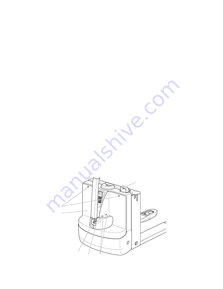
– Pull out the battery plug (1).
F
When work has to be performed under the raised fork or under the jacked up truck,
suitable measures must be taken to prevent any dropping, tilting or slipping of the fork
or truck. When lifting the truck, the instructions contained in chapter “Transportation
and commissioning” have to be observed.
When performing work on the parking brake, the truck must be secured against mov-
ing.
6.2
Removing the front cover
– Unscrew two screws (6).
– Carefully remove the front cover (3).
6.3
Removing the drive cover
The drive cover consists of two halves (3/4).
– Turn the control shaft to the right-hand stop position.
– Remove the 2 screws (2).
– Carefully remove the first cover half (3).
– Turn the control shaft to the left-hand stop position.
– Carefully unscrew and remove the second cover half (4).
1
2
3
4
5
6
7
8
9
0
Set
1
2
3
5
6
4
5
Summary of Contents for EJE 116
Page 1: ...1 2 3 4 5 6 7 8 9 0 Set Operating instructions 50425855 EJE 116 118 120 G 10 03 06 06...
Page 3: ...0108 GB...
Page 7: ...0506 GB 2...
Page 9: ...0600 GB A 2...
Page 13: ...0803 GB B 4 h 13 Ast l1 l2 Q 150 40 1268 803 h 3 55 y c l a _ 2 a _ 2 700 b 5 b 11 e Wa...
Page 17: ...0803 GB B 8...
Page 21: ...0606 GB C 4...
Page 32: ...E 3 0606 GB 1 2 3 4 5 6 7 8 0 9 S e t 5 4 3 2 1 6 7 12 8 8 9 11 10...
Page 63: ...0606 GB F 12...
Page 81: ...0506 GB 18...


