P
M
= 7 dB
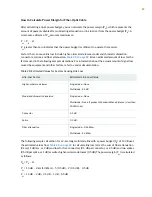
The following sample calculation for an 8-km-long single-mode link with a power budget (P
B
) of 13 dB
uses the estimated values from
to calculate link loss (LL) as the sum of fiber attenuation
(8 km @ 0.5 dB/km, or 4 dB) and loss for seven connectors (0.5 dB per connector, or 3.5 dB). The power
margin (P
M
) is calculated as follows:
P
M
= P
B
– LL
P
M
= 13 dB – 8 km (0.5 dB/km) – 7(0.5 dB)
P
M
= 13 dB – 4 dB – 3.5 dB
P
M
= 5.5 dB
In both examples, the calculated power margin is greater than zero, indicating that the link has sufficient
power for transmission and does not exceed the maximum receiver input power.
Fiber-Optic Cable Signal Loss, Attenuation, and Dispersion
IN THIS SECTION
Signal Loss in Multimode and Single-Mode Fiber-Optic Cable | 83
Attenuation and Dispersion in Fiber-Optic Cable | 84
Signal Loss in Multimode and Single-Mode Fiber-Optic Cable
Multimode fiber is large enough in diameter to allow rays of light to reflect internally (bounce off the walls
of the fiber). Interfaces with multimode optics typically use LEDs as light sources. However, LEDs are not
coherent sources. They spray varying wavelengths of light into the multimode fiber, which reflects the
light at different angles. Light rays travel in jagged lines through a multimode fiber, causing signal dispersion.
When light traveling in the fiber core radiates into the fiber cladding, higher-order mode loss results.
Together these factors limit the transmission distance of multimode fiber compared with single-mode
fiber.
Single-mode fiber is so small in diameter that rays of light can reflect internally through one layer only.
Interfaces with single-mode optics use lasers as light sources. Lasers generate a single wavelength of light,
which travels in a straight line through the single-mode fiber. Compared with multimode fiber, single-mode
fiber has higher bandwidth and can carry signals for longer distances.
83
Summary of Contents for ACX2000
Page 1: ...ACX2000 and ACX2100 Universal Metro Router Hardware Guide Published 2020 09 07 ...
Page 91: ...Front Panel of an ACX2000 Router 47 LEDs on ACX2000 and ACX2100 Routers 57 91 ...
Page 116: ...4 CHAPTER Maintaining Components Maintaining ACX2000 and ACX2100 Components 117 ...
Page 125: ...5 CHAPTER Troubleshooting Hardware Troubleshooting ACX2000 and ACX2100 126 ...
Page 139: ...139 ...
Page 144: ...Restricted Access Warning 144 ...
Page 148: ...148 ...
Page 161: ...Jewelry Removal Warning 161 ...
Page 164: ...Operating Temperature Warning 164 ...
Page 174: ...DC Power Disconnection Warning 174 ...
Page 178: ...DC Power Wiring Sequence Warning 178 ...


