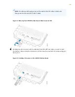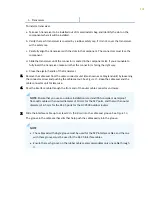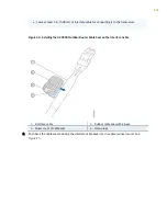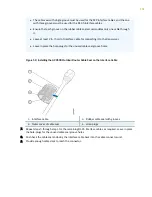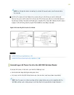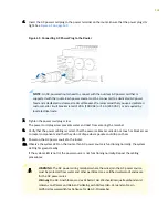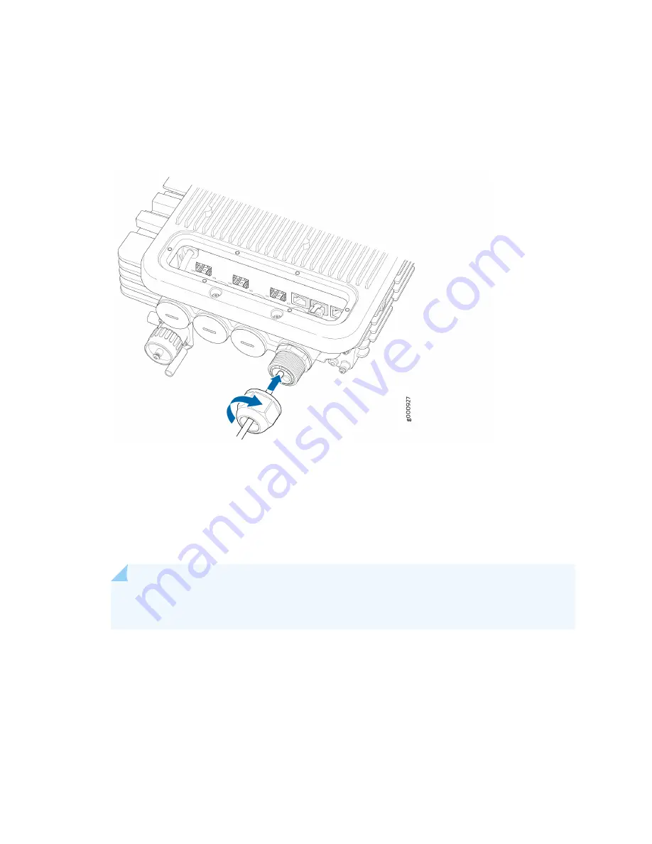
10. Tighten the connector screw’s thread end along with the cable seal inside it back into the connector
enclosure port on the router. See
Figure 21
.
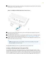
Figure 53: Installing the ACX500 Outdoor Router Connector Screw
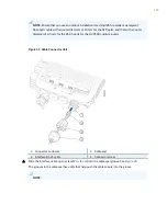
11. Insert the respective interface cable into the port. Use the interface port chamber to snap in the
RJ-45 cable into the RJ-45 port.
12. Verify that the status LEDs on the front panel indicate that the transceiver is functioning correctly.
For more information about the component LEDs, see
"LEDs on ACX500 Routers" on page 59
.
13. Replace the metal cover of the interface port chamber back to its original place, and secure it with
the six screws that were removed in step
1
.
NOTE: Ensure that the metal cover sits tightly on top of the router. Failing to do so might
allow dust and water to enter the router.
The Gigabit Ethernet RJ-45 ports are now weatherproof and are now ready to use.
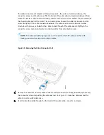
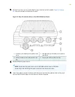
Accessing and Weatherproofing the Management Ports
In the ACX500 outdoor router, all the management ports (console, ToD, management, alarm, external
clocking 1 PPS, and USB ports) are located in a small chamber on the front bottom of the router. You can
access the management ports to access the router, to perform tasks such as monitoring, upgrading, and
so on. The metal cover locks and seals the chamber from external environmental factors. See
Figure 10
.
155

