


ACX5448, ACX5448-D, and ACX5448-M Universal Metro
Routers Quick Start Guide
IN THIS GUIDE
ACX5448, ACX5448-D, and ACX5448-M Router Description | 1
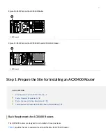
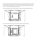
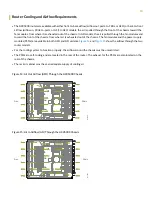
Step 1: Prepare the Site for Installing an ACX5400 Router | 7
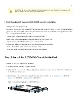
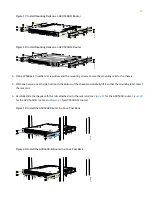
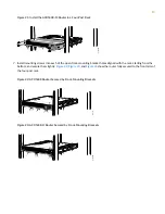
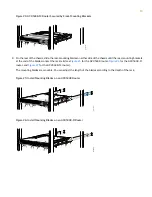
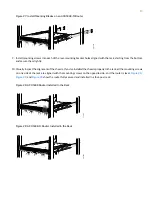
Step 2: Install the ACX5400 Chassis in the Rack | 11
Step 3: Connect the Grounding Cable | 16
Step 4: Connect Power Cables | 18
Step 5: Connect External Devices and Cables | 25
Step 6: Perform Initial Software Configuration | 28
Compliance Statements for NEBS | 33
Compliance Statements for EMC Requirements | 34
Contacting Customer Support | 35
ACX5448, ACX5448-D, and ACX5448-M Router Description
IN THIS SECTION


