background image

AI Allegro CX User’s Guide

14

Getting Started

Touchscreen Display

Use the provided stylus to tap the touchscreen and activate a software program or make a 
selection. Several system icons are available for selection that allow you to navigate. 

I

MPORTANT

:

Avoid using sharp objects that may scratch or puncture the touchscreen 

display. 

The Allegro includes a high-contrast, pressure-sensitive display with an adjustable 
backlight and heater for cold weather operation. When working in harsh conditions, such 
as a rainstorm or in high brush, pressing the 

BLUE

 shift and 

TS

 buttons toggles the 

touchscreen on or off. 

A display heater is included with the Allegro monochrome display to ensure effective 
operation throughout different temperature ranges. The heater automatically turns on at 
20 °F and turns off when the temperature is above 20 °F. Allegro color units do not require 
a heater because the unit operates effectively in all temperatures. The monochrome 
version of the Allegro displays best when the device is set up with the 

High Contrast


theme. See 

Set Display Properties for a Monochrome Display

 on page 4 for instructions. 

Recalibrate the Touchscreen Display

If the touchscreen does not respond accurately to stylus taps, recalibrate the touchscreen 
manually using the following steps: 

1

Tap 

Start

 > 

Settings

 > 

Control Panel

 > 

Stylus

 > 

Calibration

 tab. 

2

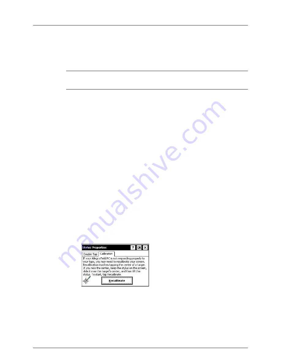
Tap 

Recalibrate

 (Figure 1-17) and then follow on-screen prompts to recalibrate 

the touchscreen. 

Figure 1-17.  Recalibrate Touchscreen

3

When the process completes, tap 

OK

 to close the window and then tap the 

Close 

icon

 (

X

) to return to the Allegro desktop. 

Summary of Contents for Allegro CX

Page 1: ...American Innovations Allegro CX Version 4 3 2 User Guide...

Page 2: ...Systems Allegro Field PC and the company logo are registered trademarks of Juniper Systems Inc Allegro MX and Allegro CX are recognized trademarks of Juniper Systems Inc Bluetooth is a registered tra...

Page 3: ...Switch 12 Overview of AI s Allegro Software 13 Touchscreen Display 14 Recalibrate the Touchscreen Display 14 Keypad and Shortcut Keys 15 System Tray Icons 18 Contacting Technical Services 20 Chapter 2...

Page 4: ...t point information 41 View Survey Records and Show Bearing to Site 42 Export a Survey File 42 Transfer a Survey File to PCS 43 Survey File Features 44 Shortcut Keys 45 Chapter 4 DC Voltage Gradient D...

Page 5: ...67 Save survey route 68 Record inspection readings 68 Timed Readings 68 Set Autosave Properties 69 Transfer a Survey Route to PCS 69 Copy a Survey Route to a Computer 70 Survey Route Features 71 Short...

Page 6: ...AI Allegro CX User s Guide vi Contents Export Control Classification Number 107 Software License 107 Index 109 Keyboard Shortcuts 113...

Page 7: ...egro Hardware page 10 System Tray Icons page 18 Contacting Technical Services page 20 Equipment List Your Allegro ships from American Innovations AI with the following items Several optional add ons a...

Page 8: ...AI perform the following tasks to prepare the device for service Install the Battery Pack see page 2 Set Display Properties for a Monochrome Display see page 4 Set Regional Settings Time Zone and Date...

Page 9: ...right to secure it in place Figure 1 2 Install Battery Pack 3 Push the battery door closed until slide latches click into place If slide latches are not securely in place the unit is no longer water t...

Page 10: ...se the window Figure 1 4 Set Battery Parameters Set Display Properties for a Monochrome Display If the Allegro includes a monochrome display complete the following steps to set display properties 1 Ta...

Page 11: ...ure 1 6 2 Set your preferred language Your Locale Use the remaining tabs to set the display style for Number Currency Time and Date Click OK to return to the Control Panel window Figure 1 6 Regional S...

Page 12: ...plete the following steps 1 Insert the Getting Started CD in the CD drive of your computer The CD is included with the Allegro If you cannot locate the CD please contact Technical Services at pcstechs...

Page 13: ...echservices aiworldwide com 2 Follow on screen prompts to install ActiveSync 3 To establish a sync connection with the Allegro and your computer follow these steps a Connect the serial cable to your c...

Page 14: ...VPN virtual private network software to establish a remote connection with a private network 1 Disable or disconnect the VPN software 2 Recycle power to the Allegro and your computer 3 Click Cancel wh...

Page 15: ...ent folder locate the folder by searching for either of the utility files Click the Windows Start button and then type wToCmd exe or CeFileXer exe in the Search field to locate the utility files and P...

Page 16: ...1 12 Optional add ons available for purchase include a GPS expansion pod with GPS antenna and a Trimble GPS receiver For a complete list of add ons available for purchase contact AI Sales at 1 800 22...

Page 17: ...pin connector Communication ports with the following characteristics Infrared port for wireless communication with a printer or computer using ActiveSync USB port for connecting to an optional USB po...

Page 18: ...er button to turn Off the device 2 If a GPS antenna cable is connected to the Allegro disconnect the cable 3 Use a coin or flathead screwdriver to loosen two screws securing the card slot door on the...

Page 19: ...3 1 is compatible with all version 6 and 7 PCS software Figure 1 16 AI Allegro Software Overview Digital Voltmeter AiDvm Close Interval CeCi Measures voltage current and resistance levels Records pot...

Page 20: ...ation throughout different temperature ranges The heater automatically turns on at 20 F and turns off when the temperature is above 20 F Allegro color units do not require a heater because the unit op...

Page 21: ...Circular keys for moving the cursor F1 through F5 keys perform softkey operations in certain software programs These keys perform special functions when used in conjunction with either the Blue or Gol...

Page 22: ...lds Left tab arrow moves cursor forward one field right tab arrow moves cursor backward one field Close Window Esc Close an open window Enable Disable Touchscreen Blue TS Disable or enable the touchsc...

Page 23: ...rrow Pan display in direction of arrow Warm Reset Soft Reboot Press and hold On Off key for about 8 seconds Release the key when the restart process begins Reset Allegro Press Tab arrow to move cursor...

Page 24: ...Data Storage Idle outlined when solid state disk is idle and not being read from or written to Data Storage Active darkens when data is being read from or written to the solid state disk PC Card indic...

Page 25: ...Getting Started 19 Heater monochrome screen only appears when touchscreen heater turns on Bluetooth Connection appears when Bluetooth is being actively used on the Allegro Table 1 3 System Tray Icons...

Page 26: ...software or Allegro or have a comment or suggestion about this manual contact Technical Services in any of the following ways Telephone 1 800 229 3404 select 1 then press 2 E mail pcstechservices aiwo...

Page 27: ...AI Allegro CX User s Guide Getting Started 21 Notes...

Page 28: ...AI Allegro CX User s Guide 22 Getting Started...

Page 29: ...ter AI DVM Topics include Safety Precautions page 23 Quick Start page 24 DVM Graph Overview page 27 Data Logger Overview page 28 Shortcut Keys page 29 Safety Precautions Observe the following safety p...

Page 30: ...negative jacks on the Allegro connector panel positive to positive negative to negative Figure 2 1 2 Click the AI DVM icon on the Allegro desktop to display the main AI DVM window Figure 2 1 Figure 2...

Page 31: ...tional add on verify Comm Port is COM3 internal and Baudrate is 9600 The option Read PPS from Internal GPS is unavailable for selection when using the Allegro internal GPS module AI DVM automatically...

Page 32: ...of time seconds minutes or hours IMPORTANT When recording an hour or more of data use the external AC power adapter to prevent draining the Allegro battery The automatic power down feature of the All...

Page 33: ...lable 5 number of satellites in view P PPS time signal has been received Z ZDA message has been received 1 7 9 10 Shaded area represents on cycle non shaded area represents off cycle Status line with...

Page 34: ...rently during setup data logger files save in the DvmData folder by default To access the folder double tap My Computer C_Drive BTS DvmData The data logger file includes the following information Figu...

Page 35: ...plays the Options window Voltage Range CTRL Up CTRL Down Alt U or U Adjust the voltage range or select auto ranging To increase select CTRL Up to decrease CTRL Down and to auto range select ALT U VDC...

Page 36: ...ist Move cursor to Ok and then press Enter to apply changes Move cursor to Cancel and then press Enter to cancel changes Open Graph Remarks Window and Add Data Tab Save Enter Press Tab to move cursor...

Page 37: ...AI Allegro CX User s Guide Digital Voltmeter AI DVM 31 Notes...

Page 38: ...AI Allegro CX User s Guide 32 Digital Voltmeter AI DVM...

Page 39: ...measures voltage using the digital voltmeter card inside the Allegro This chapter explains how to set up and use AI s close interval software CeCi Topics include Quick Start page 34 Set Survey File O...

Page 40: ...cord inspection readings page 38 Connect test leads to the Allegro CeCi software records potential readings using the Allegro digital voltmeter and either a data cane or wire counter connected to the...

Page 41: ...this field empty Tech Enter the surveyor s name in this optional field If you plan to transfer the survey file to PCS the surveyor s name populates the Surveyor field in the Indirect Survey Manager IS...

Page 42: ...F5 or Ctrl P on the Allegro keypad will also pause or resume timed readings 5 If you want to monitor the number of reads per flag tap Monitor record count per flag and then click the drop down arrow i...

Page 43: ...nsition times the last available reading before the transition is recorded 4 If you are taking an interrupted survey using GPS synchronized current interrupters complete the following steps a Tap the...

Page 44: ...how often coordinates are included with readings 3 Tap Record time of reading to include a GPS time stamp with readings 4 If you are using a second GPS receiver dual GPS complete the following steps...

Page 45: ...ou specify tap Beep for voltages less negative than this value and enter a warning value in the Voltage level field 3 Tap Beep when overwrite existing data if you want the Allegro to beep when a surve...

Page 46: ...Select an option in the list and then a color in the color grid Repeat this step for each item in the list you want to assign a color For example to have readings display in red text in the survey fil...

Page 47: ...remark 1 Select a survey record and then tap Remark in the main menu 2 Double tap a remark or enter the remark s code number CeCi inserts the remark in the remarks field of the currently selected reco...

Page 48: ...conditions occur The difference in latitude and longitude is more than 5 degrees Latitude is above 85 degrees north or below 85 degrees south Also expressed as 85 90N degrees latitude northern hemisph...

Page 49: ...dock connect the USB cable to the power dock and your computer 2 At your computer start WMDC or ActiveSync Follow on screen prompts to establish communications For ActiveSync users click No when prom...

Page 50: ...and you view the survey file in Single record mode coordinates display in the survey remarks field 3 Current GPS coordinates If satellite communication has not been established GPS invalid displays Wh...

Page 51: ...lays the File Open window Save Ctrl S Saves the survey Flag Marker F Inserts a flag marker Reset Flag Count Ctrl F Reset Flag Count Gap Marker G Inserts a gap marker in Flagged mode Capture Reading En...

Page 52: ...dow Ok Cancel Ok Cancel Press Ok to apply changes or Cancel to cancel changes Navigate Open and Save As Windows Tab Up Down Arrows and Home End Arrows Press Tab to move cursor between fields Press Up...

Page 53: ...e Press W to move cursor to Width Navigate Colors Tab E Tab Up Down Arrows Home End Arrows Press E to enable or disable Enable Color in the Colors tab of Options With Enable Color enabled Press Tab to...

Page 54: ...AI Allegro CX User s Guide 48 Close Interval Survey CeCi Notes...

Page 55: ...the following list Quick Start page 49 Survey File Options page 54 Add Remarks Indication and Test Point Information page 56 View Survey Records and Show Bearing to Site page 57 Export a Survey File...

Page 56: ...f the indication Complete the following steps 1 Plug data canes in the red positive and black negative jacks on the Allegro connector panel positive to positive negative to negative Figure 4 1 2 Click...

Page 57: ...peline Code in PCS If the ROW Code entered earlier includes multiple parallel pipelines with different pipeline codes enter the appropriate pipeline code If pipeline codes have not been created in PCS...

Page 58: ...page 52 Set fixed increment mode properties 1 Tap Metric if you want readings recorded in meters instead of feet 2 Enter the distance between reads in the Increment field 3 Click the drop down arrow...

Page 59: ...directional arrow to display in the main DCVG window indicating the polarity of the reading during the survey Set GPS properties 1 Tap the GPS tab 2 Tap Record GPS Location to include coordinates with...

Page 60: ...the following list Set optional audio and double click properties page 54 Set optional autosave properties page 55 Set optional GPS properties page 55 Set optional color properties page 55 Set optiona...

Page 61: ...n after and enter the number of seconds in the seconds without updates field When GPS coordinates are older than 30 seconds DCVG displays the time since the last GPS update When GPS coordinates are ol...

Page 62: ...he remarks field of the currently selected record You can also enter your own remark in the remarks field of the survey file Add indication information 1 Tap View Test Point Info when an indication is...

Page 63: ...View Survey Records and Show Bearing to Site You can view survey records either as a list or single record Tap View Single record or List When viewing a single record with GPS coordinates double tap...

Page 64: ...er software applications such as Microsoft Excel To export a survey file follow these steps 1 Tap File Export 2 Tap the Type field and select an export format from the list of options 3 Tap OK to clos...

Page 65: ...h indication data number type signal strength and remarks Single record mode Remark field with recorded indication data Second remark field displays with GPS coordinates when set up in On Off GPS Sync...

Page 66: ...Save Ctrl S Saves the survey Flag Marker F Enters an F in the record to show a Flag Gap G Enters a G in the record to show a Gap Capture Reading Enter Captures a reading Go to first record CTRL Home M...

Page 67: ...AI Allegro CX User s Guide DC Voltage Gradient DCVG 61 Notes...

Page 68: ...AI Allegro CX User s Guide 62 DC Voltage Gradient DCVG...

Page 69: ...ng a survey data is then transferred from the Allegro back to PCS NOTE The PCS survey route includes information and reading fields for ROW right of way facilities to be surveyed For information about...

Page 70: ...e survey route page 68 Record inspection readings page 68 Connect test leads to the Allegro PS records facility inspection readings using the Allegro digital voltmeter and a data cane connected to the...

Page 71: ...and Cycle begins with fields This survey type requires that you also set up properties in the GPS tab View Options GPS tab If on off time settings are incorrect for either High Low or GPS Sync an err...

Page 72: ...provide a time stamp with readings Add or delete a new site Complete the following steps to add or delete a new site New sites added on the Allegro are marked with a bullet in the Site List and can b...

Page 73: ...rarchy labeled From Allegro f Tap the Milepost field and enter the new site s milepost number g Enter data for the new site in the Information fields Information and Reading fields are separated with...

Page 74: ...ing in the survey file Timed Readings When the survey route is set up in PCS with Allegro prompts for the following fields these same fields are available in PS for timed readings Min P S Max P S Aver...

Page 75: ...t the provided serial cable to your computer and the Allegro If you are using a USB power dock connect the USB cable to the power dock and your computer 2 At your computer start WMDC or ActiveSync Fol...

Page 76: ...No when prompted to create a Partnership Clicking No allows you to create a Guest connection instead 3 In WMDC point the mouse at File Management and then click Browse the contents of your device In A...

Page 77: ...splay the last recorded reading if included in the PCS route file 2nd status pane displays GPS DGPS HILO or DVM range and function based on the On Off Method setup in the survey file View Options On O...

Page 78: ...d reading field and press Enter to set up start stop or cancel timed reading mode Record GPS Coordinates F4 Records GPS coordinates when cursor is in a reading field Insert GPS Coordinates F4 Insert G...

Page 79: ...u Alt E Opens Edit menu Open View Menu Alt V Opens View menu Navigate Information and Reading Fields Alt U Moves cursor between information and reading fields Navigate any Window or Tab Tab Up Down Ar...

Page 80: ...AI Allegro CX User s Guide 74 Annual Periodic Survey Periodic Survey Notes...

Page 81: ...w survey mode until the satellite signal is re acquired Table A 1 Suggested On Off Settings On Off High Low setup for 1 second cycle A minimum maximum reading from a sample of readings Of the remainin...

Page 82: ...e reading is equal to the on reading and the most positive reading is equal to the off reading A snapshot of readings in a certain time period 0 7 on 0 3 off 0 8 on 0 2 off 200 mSec On Setup 150 mSec...

Page 83: ...c Off Delay Starts reading 200 mSec into on cycle off to on Starts reading 250 mSec into off cycle on to off GPS RT Setup Time 50 mSec No readings 50 mSec before off cycle to Off Delay No readings 50...

Page 84: ...AI Allegro CX User s Guide 78 Recommendations for Interrupted On Off Settings Notes...

Page 85: ...which version of software is installed on the Allegro The software version is listed in the About window of each AI software For example start CeCi and then tap View About CeCi The first line of infor...

Page 86: ...egro GPS patch antenna is plugged in the GPS ANT connector on the Allegro The Allegro includes an internal GPS module that uses the patch antenna to acquire a GPS timing signal from the satellite If t...

Page 87: ...crease the contrast and brightness To decrease the contrast and brightness press Orange F4 keys simultaneously How do I find the version number of the DVM card To determine the version of the DAQ card...

Page 88: ...the GPS Status software and verify COM port settings are correct Run the GPS Pod Setup software and verify settings are correct All software must be closed before viewing settings in GPS Pod Setup Ve...

Page 89: ...h several times before taking survey readings This allows you to change on off delay times as needed to get the best on off capture How do I include Remarks and GPS coordinates in a CeCi survey file w...

Page 90: ...d by tapping the field or pressing the Tab button right arrow 3 Tap Remark to open the Remarks window Select and then double tap the remark to insert it in the survey record and close the window 4 Pre...

Page 91: ...ad crossing exposed pipe and so on 6 Press Ctrl Z to toggle from SKIP to normal mode Move the cursor to the Remarks field and add another remark 7 Press Enter and then the down arrow to move to the ne...

Page 92: ...AI Allegro CX User s Guide 86 FAQs...

Page 93: ...AI Allegro CX User s Guide FAQs 87 Notes...

Page 94: ...AI Allegro CX User s Guide 88 FAQs...

Page 95: ...ount of time since the last GPS fix and current GPS time enable the Offset option to view the distance between two points enable the Beep option if you want the Allegro to beep when GPS readings updat...

Page 96: ...ield Description Satellites Current number of satellites tracked by the GPS receiver display in this status line If using dual GPS status line displays the number of satellites as Satellites in view T...

Page 97: ...nd baud rate GPS coordinates Shows longitude latitude and elevation coordinates received from a minimum of 3 satellites Coordinates update every second With a clear view of the sky GPS accuracy withou...

Page 98: ...t and may include the suffix letters P and or Z P indicates a PPS one pulse per second time signal is being received Z indicates a GPS time packet is being received When GPS time is unavailable or the...

Page 99: ...COM port and baud rate Tap Read PPS from Internal GPS if you want to use the Allegro internal GPS module for the PPS timing signal Select a GPS display format Degrees and Minutes or Decimal degrees C...

Page 100: ...on Navigating GPS Status Software Tab Enter and Up Down Arrows Press Tab to move cursor from one field to another Press Enter to open or close a drop down list Press Up Down Arrows to move cursor in a...

Page 101: ...sition fixes are more accurate however satellite fixes occur less often Signal Acquisition This method provides satellite fixes in a wider range of conditions It accepts a higher level of position unc...

Page 102: ...rive C_Program Files GPSPodSetup to display the Gps GPS Receiver Port Settings window Figure C 3 GPS Receiver Port Settings 2 Tap Get Settings and complete the following steps a Click the drop down ar...

Page 103: ...d then on again Run Save System when you change option or preference settings in any of the AI Allegro software or install new software on the Allegro To run Save System follow these steps 1 Tap Start...

Page 104: ...legro or using AI software Use Set DAQ Registry Keys to recreate DAQ registry keys on the Allegro when any of the following error messages display Unidentified PC card adapter DAQ card unavailable Err...

Page 105: ...AI Allegro CX User s Guide Utility Software 97 Notes...

Page 106: ...AI Allegro CX User s Guide 98 Utility Software...

Page 107: ...101 Set Up a Holux GPS Receiver The following procedure explains how to use the GPS Status software to set up a Holux GR213 receiver modified by Juniper Systems for use with the Allegro Complete the f...

Page 108: ...no parity and 1 stop bit The receiver uses the WGS84 Datum Install GPS Controller Software The installation CD provided with the GPS receiver includes a copy of Trimble s GPS Controller software You c...

Page 109: ...der ProXRT Receiver GPS Pathfinder ProXT Receiver NOTE If the GPS receiver uses Bluetooth for communication also refer to Save System on page 95 for additional information Complete the following steps...

Page 110: ...User s Guide 102 GPS Receivers b Double tap the GPS Controller icon on the Allegro to display the Skyplot window Figure D 2 Figure D 2 Skyplot 4 Tap Skyplot Setup GPS Settings Figure D 3 Figure D 3 S...

Page 111: ...ollowing fields as follows When you finish tap OK to return to the Setup window Figure D 3 Velocity Filter Auto Receiver Power Output On NEMA Output On Figure D 4 Setup GPS Settings 6 Tap Options Conn...

Page 112: ...tput Settings window using information in the next table Table D 1 When you finish tap OK Tap OK again to return to the Setup Options window Figure D 5 Table D 1 NMEA Output Settings Field XRT XB XH X...

Page 113: ...u finish tap OK to return to the Setup Options window Figure D 5 11 Click Setup Skyplot to view GPS satellite information 12 Tap Skyplot Setup Options Disconnect from GPS Tap Yes when the following me...

Page 114: ...AI Allegro CX User s Guide 106 GPS Receivers Notes...

Page 115: ...erty rights therein are exclusively owned by AI and as may be applicable AI s licensors This Agreement does not grant you any rights in or to the source code of the AI Software All rights not expressl...

Page 116: ...uired by or on behalf of a civilian agency shall be subject to the terms of this commercial computer software license as specified in 48 C F R 12 212 of the Federal Acquisition Regulations and its suc...

Page 117: ...34 CI survey file color settings 40 graph settings 40 CI survey mode 35 Close interval software 33 COM port unable to open 88 Compromise 93 Connector panel 10 11 D DAQ card data acquisition 23 DAQ ca...

Page 118: ...7 waveform graph 27 DVM data logger battery usage 26 E Export CI survey file 42 External shunt 23 F Fixed increment CI survey 36 Flagged CI survey 36 Function 23 G Global positioning system 100 GPS 10...

Page 119: ...m 95 Screen protector 2 Serial communication cable 1 Set DAQ registry 96 Show bearing to site 42 57 Shunt external 23 Signal acquisition 93 Stick adapter data cane 12 Stylus 1 Survey file options 39 S...

Page 120: ...de 112 Index GPS pod setup 87 GPS status 87 Key Redirect 87 Save system 87 Set DAQ registry 87 V V button dcvg reading 53 voltage 53 VDOP value 89 W Waveform graph 27 Windows Mobile Device Center 2 6...

Page 121: ...ndow to add a new line press Tab to move cursor to Ok or Cancel and then press Enter New Ctrl N Create new survey file Open Ctrl O Open File Open window Save Ctrl S Save survey file Flag Marker F Inse...

Page 122: ...w Test Point Information Ctrl T Open Test Point Information window DCVG Open Ctrl O Open File Open window Save Ctrl S Save survey file Copy Cut Paste Ctrl C Ctrl X Ctrl V Copy selection to clipboard R...

Reviews: