background image

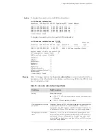
  Received:
    0 packets
    0 bytes
    1 error
    0 discards
  Sent:
    0 packets
    0 bytes
    0 errors
    0 discards
received mtu 0
queue 0: traffic class best-effort, bound to ethernet FastEthernet2/0
    Queue length 0 bytes
    Forwarded packets 0, bytes 0
    Dropped committed packets 0, bytes 0
    Dropped conformed packets 0, bytes 0
    Dropped exceeded packets 0, bytes 0
MPLS policy input shimRl
    classifier-group *
      0 packets, 0 bytes
      rate-limit-profile shimRl
        committed: 0 packets, 0 bytes
        conformed: 0 packets, 0 bytes
        exceeded:  0 packets, 0 bytes
  MPLS policy output shimRl
    classifier-group *
      0 packets, 0 bytes
      rate-limit-profile shimRl
        committed: 0 packets, 0 bytes
        conformed: 0 packets, 0 bytes
        exceeded:  0 packets, 0 bytes

This excerpt from the command output shows the label information displayed when
a circuit is up

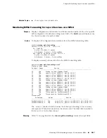
host1#

show mpls l2transport interface

...
  Out Label 49 on  tun mpls:lsp-de090100-24-37
    0 pkts, 0 hcPkts, 0 octets
    0 hcOctets, 0 errors, 0 discardPkts
    queue 0: traffic class best-effort, bound to atm-vc ATM1/0.1
      Queue length 0 bytes 
      Forwarded packets 0, bytes 0
      Dropped committed packets 0, bytes 0
      Dropped conformed packets 0, bytes 0
      Dropped exceeded packets 0, bytes 0
...

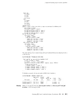
To display summary information about MPLS shim interfaces:

host1#

show mpls interface shim brief

                    Remote-PE   Virtual     Load
                       or       Circuit   Balancing    Admin    Oper
    Interface       LSP-name      ID        Group      state    state
-----------------   ---------   -------   ---------   -------   -----
FastEthernet2/0.1   222.9.1.3   200001    -           enabled   up
FastEthernet2/0.2   222.9.1.3   200002    -           enabled   up

Meaning

Table 73 on page 570 lists the 

show mpls interface

 and 

show mpls l2transport

interface

 command output fields

Monitoring MPLS Layer 2 Interfaces for Layer 2 Services over MPLS

569

Chapter 8: Monitoring Layer 2 Services over MPLS

Summary of Contents for BGP

Page 1: ...ware for E Series Routing Platforms BGP and MPLS Configuration Guide Release 11 1 x Juniper Networks Inc 1194 North Mathilda Avenue Sunnyvale California 94089 USA 408 745 2000 www juniper net Published 2010 03 30 ...

Page 2: ...333 650 6 359 479 6 406 312 6 429 706 6 459 579 6 493 347 6 538 518 6 538 899 6 552 918 6 567 902 6 578 186 and 6 590 785 JUNOSe Software for E Series Routing Platforms BGP and MPLS Configuration Guide Release 11 1 x Copyright 2010 Juniper Networks Inc All rights reserved Printed in USA Writing Subash Babu Asokan Bruce Gillham Brian Wesley Simmons Fran Singer Megha Shaseendran Krupa Chandrashekar ...

Page 3: ...ealms devices links ports or transactions or require the purchase of separate licenses to use particular features functionalities services applications operations or capabilities or provide throughput performance configuration bandwidth interface processing temporal or geographical limits In addition such limits may restrict the use of the Software to managing certain kinds of networks or require ...

Page 4: ...in connection with such withholding taxes by promptly providing Juniper with valid tax receipts and other required documentation showing Customer s payment of any withholding taxes completing appropriate applications that would reduce the amount of withholding tax to be paid and notifying and assisting Juniper in any audit or tax proceeding related to transactions hereunder Customer shall comply w...

Page 5: ...nted to in writing by the party to be charged If any portion of this Agreement is held invalid the Parties agree that such invalidity shall not affect the validity of the remainder of this Agreement This Agreement and associated documentation has been written in the English language and the Parties agree that the English version will govern For Canada Les parties aux présentés confirment leur volo...

Page 6: ...vi ...

Page 7: ...9 Part 3 Layer 2 Services Over MPLS Chapter 6 Layer 2 Services over MPLS Overview 509 Chapter 7 Configuring Layer 2 Services over MPLS 529 Chapter 8 Monitoring Layer 2 Services over MPLS 563 Part 4 Virtual Private LAN Service Chapter 9 VPLS Overview 575 Chapter 10 Configuring VPLS 589 Chapter 11 Monitoring VPLS 613 Part 5 Virtual Private Wire Service Chapter 12 VPWS Overview 645 Chapter 13 Configu...

Page 8: ...viii JUNOSe 11 1 x BGP and MPLS Configuration Guide ...

Page 9: ... BGP Routing 3 Overview 3 Conventions in This Chapter 3 Autonomous Systems 4 BGP Speaker 5 BGP Peers and Neighbors 5 BGP Session 5 IBGP and EBGP 6 Interior Gateway Protocols 6 BGP Messages 7 BGP Route 8 Routing Information Base 8 Prefixes and CIDR 9 Path Attributes 10 Transit and Nontransit Service 11 IPv6 BGP Support 12 Exchange of IPv6 Routing Information over TCP IPv4 12 Exchange of IPv6 Routin...

Page 10: ...BGP for Overload Conditions 40 Enabling Route Storage in Adj RIBs Out Tables 41 Effects of Changing Outbound Policies 42 Configuring the Address Family 43 Enabling Lenient Behavior 46 Configuring Promiscuous Peers and Dynamic Peering 47 Configuring Passive Peers 49 Advertising Routes 50 Prefixes Originating in an AS 50 Advertising Best Routes 52 Redistributing Routes into BGP 53 Redistributing Rou...

Page 11: ...ommand 112 Using a Route Map 113 Using an AS Path Access List 113 Configuring the Local Pref Attribute 115 Using the bgp default local preference Command 116 Using a Route Map to Set the Local Preference 117 Understanding the Origin Attribute 117 Understanding the AS Path Attribute 120 Configuring a Local AS 121 Configuring the MED Attribute 122 Missing MED Values 125 Comparing MED Values Within a...

Page 12: ...tacking 212 MPLS Labels and Label Spaces 212 TTL Processing in the Platform Label Space 213 TTL Processing on Incoming MPLS Packets 214 TTL Processing on Outgoing MPLS Packets 215 MPLS Rules for TTL Expiration 217 MPLS Label Distribution Methodology 218 Mapping IP Data Packets onto MPLS LSPs 220 Statistics for IP Packets Moving On or Off MPLS LSPs 222 MPLS Forwarding and Next Hop Tables 224 Spoof ...

Page 13: ...Engineering 243 LSP Backup 243 Path Option 244 Reoptimization 244 Methods for Configuring RSVP TE Tunnels 244 Tracking Resources for MPLS Traffic Engineering 244 Starting Admission Control 245 Admission Control Interface Table 245 Configuring Traffic Engineering Resources 245 LSP Preemption 246 Topology Driven LSPs 246 LDP over RSVP TE 246 LDP Graceful Restart 247 LDP IGP Synchronization 249 Synch...

Page 14: ...PLS Interface Configuration Tasks 274 MPLS Interface Tasks 274 LDP Interface Tasks 275 RSVP TE Interface Tasks 275 MPLS Tunnel Configuration Tasks 276 MPLS Tunnel Profile Configuration Tasks 277 Configuring Explicit Routing for MPLS 279 Defining Configured Explicit Paths 280 Specifying Configured Explicit Paths on a Tunnel 280 Configuring Dynamic Explicit Paths on a Tunnel 281 Additional LDP Confi...

Page 15: ...r MPLS Forwarding Table Statistics 317 Enabling and Setting a Baseline for MPLS Next Hop Table Statistics 318 Setting a Baseline for MPLS Tunnel Statistics 318 Enabling Statistics Collection for Policies Attached to MPLS Tunnels 318 Clearing and Re Creating Dynamic Interfaces from MPLS Major Interfaces 319 Clearing and Refreshing IPv4 Dynamic Routes in the Tunnel Routing Table 319 Clearing and Ref...

Page 16: ... Sending an MPLS Echo Request Packet to an L3VPN IP or IPv6 Prefix 368 Tracing the Path of an MPLS Echo Request Packet to an L3VPN IP or IPv6 Prefix 369 Sending an MPLS Echo Request Packet to an RSVP TE Tunnel 369 Tracing the Path of an MPLS Echo Request Packet to an RSVP TE Tunnel 369 Sending an MPLS Echo Request Packet to a VPLS Instance 369 Tracing the Path of an MPLS Echo Request Packet to a V...

Page 17: ...ces Across Multiple Autonomous Systems 405 Using Route Targets to Configure VPN Topologies 406 Full Mesh VPNs 406 Hub and Spoke VPNs 407 Overlapping VPNs 408 Constraining Route Distribution with Route Target Filtering 410 Exchanging Route Target Membership Information 411 Receiving and Sending RT MEM NLRI Routing Updates 412 Conditions for Advertising RT MEM NLRI Routes 414 Advertising a Default R...

Page 18: ... Route Importation 452 Deleting Routes for a VRF 453 Enabling VRF to VR Peering 454 Achieving Fast Reconvergence in VPN Networks 455 Fast Reconvergence with Unique RDs 456 Fast Reconvergence by Means of Reachability Checking 457 Configuring BGP to Send Labeled and Unlabeled Unicast Routes 458 BGP Next Hop Self 459 BGP Processing of Received Routes 460 Labeled Unicast Routes 460 Unlabeled Unicast R...

Page 19: ...ttribute 481 Distributing OSPF Routes from PE Router to CE Router 481 Preventing Routing Loops 482 Using Remote Neighbors to Configure OSPF Sham Links 482 OSPF Backdoor Links 483 OSPF Sham Links 483 Configuration Tasks 485 Configuring VPLS 487 Configuring L2VPNs 487 Monitoring BGP MPLS VPNs 487 Part 3 Layer 2 Services Over MPLS Chapter 6 Layer 2 Services over MPLS Overview 509 Layer 2 Services ove...

Page 20: ...N Layer 2 Services 531 Configuring S VLAN Tunnels for Layer 2 Services 532 Configuring Local Cross Connects Between Ethernet VLAN Interfaces 533 Configuring Local ATM Cross Connects with AAL5 Encapsulation 534 Configuring an MPLS Pseudowire with VCC Cell Relay Encapsulation 536 Configuring HDLC Layer 2 Services 538 Configuring Local Cross Connects for HDLC Layer 2 Services 539 Configuring CE Side ...

Page 21: ...for Layer 2 Services over MPLS 568 Part 4 Virtual Private LAN Service Chapter 9 VPLS Overview 575 VPLS Overview 575 VPLS Components 576 VPLS Domains 576 Customer Edge Devices 577 VPLS Edge Devices 577 VPLS and Transparent Bridging 577 BGP Signaling for VPLS 579 LDP Signaling for VPLS 579 Targeted Sessions 579 PWid FEC Element TLV 580 BGP Multihoming for VPLS 580 Selecting the Designated VE Device ...

Page 22: ...LS 613 Setting a Baseline for VPLS Statistics 614 Setting a Baseline for a VPLS Instance 614 Setting a Baseline for a Network Interface Associated with a VPLS Instance 614 Setting a Baseline for the VPLS Virtual Core Interface Associated with a VPLS Instance 614 Clearing Dynamic MAC Addresses from the VPLS Forwarding Table 615 Clearing All Dynamic MAC Addresses from the VPLS Forwarding Table 615 C...

Page 23: ...rivate Wire Service Chapter 12 VPWS Overview 645 VPWS Overview 645 BGP Signaling for L2VPNs 647 VPWS Components 648 VPWS Instances 648 Customer Edge Devices 649 VPWS Provider Edge Devices 649 VPWS and BGP MPLS VPNs 649 BGP Multihoming for VPWS 650 Selecting the Designated VE Device for a Multihomed Site 652 Multihoming Reaction to Failures in the Network 654 VPWS Supported Features 655 VPWS Platfo...

Page 24: ... BGP Route Flap Dampening Information for the L2VPN Address Family 672 Clearing the Wait for the End of RIB Marker for the L2VPN Address Family 672 Monitoring BGP Related Settings for VPWS L2VPNs 673 Monitoring BGP Next Hops for VPWS L2VPNs 677 Monitoring VPWS Connections 679 Monitoring VPWS Instances 681 Monitoring L2VPN Interfaces for VPWS 684 Monitoring MPLS Forwarding Table for VPWS 686 Part 6...

Page 25: ...Route When Another Route is Absent 68 Figure 20 Advertising a Default Route When Another Route is Present 70 Figure 21 Filtering with Access Lists 84 Figure 22 Filtering Routes with an Access List 84 Figure 23 Filtering with AS Path Access Lists 88 Figure 24 Assigning a Filter List 89 Figure 25 Route Map Filtering 91 Figure 26 Communities 93 Figure 27 Community Lists 96 Figure 28 Configuring Next ...

Page 26: ... for All Pushed Labels 262 Figure 61 Simple MPLS Domain 264 Chapter 3 Configuring MPLS 267 Figure 62 FEC Aggregation and Equal Cost Paths 282 Figure 63 Bypass Tunnel 289 Figure 64 Differentiated Services over an MPLS Network 301 Figure 65 Associations Between PHB ID EXP Bits and Traffic Classes Colors 306 Figure 66 Signaled Mapping 307 Chapter 4 Monitoring MPLS 315 Figure 67 Sample MPLS L3VPN Topo...

Page 27: ...Route for Internet Access 463 Figure 102 Fallback Global Option 464 Figure 103 Global Import Map Applied to Routes Imported from VRF BGP RIB 465 Figure 104 BGP Session Between CE Router and Parent VR 466 Figure 105 Static Route to Shared IP Interface 468 Figure 106 Global Export Map Applied to Routes Exported from VRF BGP RIB 469 Figure 107 Carrier of Carriers Internet Service 471 Figure 108 Carri...

Page 28: ... a SIngle Pseudowire 560 Part 4 Virtual Private LAN Service Chapter 9 VPLS Overview 575 Figure 128 VPLS Sample Topology 576 Chapter 10 Configuring VPLS 589 Figure 129 Topology for VPLS Configuration Example with BGP Signaling 602 Figure 130 Topology for VPLS Configuration Example with LDP Signaling 609 Part 5 Virtual Private Wire Service Chapter 12 VPWS Overview 645 Figure 131 VPWS Sample Topology...

Page 29: ...es and Default Next Hop Addresses for Various Configurations 31 Table 14 Commands That Create Match and Set Route Maps 71 Table 15 Clauses Supported in BGP Match and Set Route Maps 71 Table 16 Commands That Create Match Only Route Maps 72 Table 17 Clauses Not Supported in BGP Route Maps 72 Table 18 Set Clauses Supported in Route Maps Applied with the Table Map Command 81 Table 19 Action Based on W...

Page 30: ...able 50 show mpls minor interface Output Fields 351 Table 51 show mpls next hop Output Fields 352 Table 52 show mpls phb id Output Fields 353 Table 53 show mpls profile Output Fields 354 Table 54 show mpls rsvp Output Fields 355 Table 55 show mpls rsvp authentication Output Fields 358 Table 56 show mpls rsvp bfd interfaces Output Fields 359 Table 57 show mpls rsvp counters Output Fields 360 Table ...

Page 31: ...13 Table 84 Commands for Monitoring VPLS Bridging Settings 617 Table 85 show bridge Output Fields 619 Table 86 show bridge groups details Output Fields 621 Table 87 show bridge interface Output Fields 623 Table 88 show bridge interface Output Fields 625 Table 89 show bridge interface vpls Output Fields 625 Table 90 show bridge port Output Fields 628 Table 91 show bridge port brief Output Fields 62...

Page 32: ... Table 106 show ip bgp l2vpn all next hops Output Fields 678 Table 107 show l2vpn connections Output Fields 681 Table 108 show l2vpn instance Output Fields 683 Table 109 show l2vpn interface Output Fields 684 Table 110 show mpls forwarding Output Fields 687 xxxii List of Tables JUNOSe 11 1 x BGP and MPLS Configuration Guide ...

Page 33: ...mation in the latest release notes differs from the information in the documentation follow the JUNOSe Release Notes To obtain the most current version of all Juniper Networks technical documentation see the product documentation page on the Juniper Networks website at http www juniper net techpubs Audience This guide is intended for experienced system and network specialists working with Juniper ...

Page 34: ...pf 2 Routing Process OSPF 2 with Router ID 5 5 0 250 Router is an Area Border Router ABR Represents information as displayed on your terminal s screen Fixed width text like this There are two levels of access user and privileged clusterId ipAddress Appendix A System Specifications Emphasizes words Identifies variables Identifies chapter appendix and book names Italic text like this Press Ctrl b In...

Page 35: ...e from the Juniper Networks Web site athttp www juniper net Documentation Feedback We encourage you to provide feedback comments and suggestions so that we can improve the documentation to better meet your needs Send your comments to techpubs comments juniper net or fill out the documentation feedback form at https www juniper net cgi bin docbugreport If you are using e mail be sure to include the...

Page 36: ...ase notes http www juniper net customers csc software Search technical bulletins for relevant hardware and software notifications https www juniper net alerts Join and participate in the Juniper Networks Community Forum http www juniper net company communities Open a case online in the CSC Case Management tool http www juniper net cm To verify service entitlement by product serial number use our S...

Page 37: ...Part 1 Border Gateway Protocol Configuring BGP Routing on page 3 Border Gateway Protocol 1 ...

Page 38: ...2 Border Gateway Protocol JUNOSe 11 1 x BGP and MPLS Configuration Guide ...

Page 39: ...s on page 133 Detecting Peer Reachability with BFD on page 141 Managing a Large Scale AS on page 143 Configuring BGP Multicasting on page 153 Using BGP Routes for Other Protocols on page 156 Configuring BGP MPLS VPNs on page 157 Testing BGP Policies on page 157 Monitoring BGP on page 158 Overview The Border Gateway Protocol BGP provides loop free interdomain routing between autonomous systems ASs ...

Page 40: ...l pref MULTI_EXIT_DISC multiexit discriminator or MED NEW_AS_PATH new as path NEW_AGGREGATOR new aggregator NEXT_HOP next hop or next hop NO_ADVERTISE no advertise NO_EXPORT no export NO_EXPORT_SUBCONFED no export subconfed NOTIFICATION notification OPEN open ORIGIN origin ORIGINATOR_ID originator ID ROUTE REFRESH route refresh UPDATE update Autonomous Systems An autonomous system AS is a set of r...

Page 41: ...et of BGP peers with which it exchanges routing information BGP peers do not have to be directly connected to each other in order to share a BGP session Another term for BGP peer is BGP neighbor A BGP peer group consists of two or more BGP peers that share a common set of update policies In Figure 1 on page 5 router NY and router Chicago are peers Router NY and router LA are peers Router NY and ro...

Page 42: ...IBGP and EBGP sessions but the rules for when to send which message and how to interpret each message differ slightly for this reason some people refer to IBGP and EBGP as two separate protocols IBGP requires that BGP speakers within an autonomous system be fully meshed meaning that there must be a BGP session between each pair of peers within the AS IBGP does not require that all the peers be phy...

Page 43: ...ying TCP session has been established is an open message This message contains various bits of information that enable the two BGP peers to determine whether they want to establish a BGP session with each other for example the AS number of the BGP speaker and to negotiate certain parameters for the BGP session for example how often to send a keepalive message Update messages The update message is ...

Page 44: ...vely resetting the session 4 Connection Rejected The BGP speaker is rejecting the connection for example because the peer is not configured locally on the speaker after accepting a transport protocol connection 5 Other Configuration Change The BGP speaker is administratively resetting the session for some other configuration 6 Route refresh messages BGP speakers can send route refresh messages to ...

Page 45: ... of classful addresses such as Class A Class B and Class C in the Internet Classful addresses have an implicit fixed length mask corresponding to the predefined class boundaries For example 192 56 0 0 is a Class B address with an implicit or natural mask of 255 255 0 0 CIDR uses network prefixes and explicit masks represented by a prefix length enabling network prefixes of arbitrary lengths CIDR r...

Page 46: ...han one route to the same destination prefix it selects one of those routes to use the best route based on the path attributes BGP as implemented on the Juniper Networks E Series Broadband Services Router specifies detailed and complex criteria for picking the best route this helps ensure that all routers will converge to the same routing table a necessary behavior to avoid routing loops See Selec...

Page 47: ...not deaggregate the prefix A BGP speaker aggregating routes can include the aggregator attribute to indicate the router and AS where the aggregation was performed Community and extended community identify prefixes as sharing some common attribute providing a means of grouping prefixes and enacting routing policies on the group of prefixes A prefix can belong to more than one community You can spec...

Page 48: ... the IPv6 address family such as policy based routing redistributing routes to and from other protocols route aggregation route flap dampening and confederations For a description of IPv6 see Configuring IPv6 in JUNOSe IP IPv6 and IGP Configuration Guide Multiprotocol Extensions for BGP 4 MP BGP allow the exchange of IPv6 routing information over TCP IPv4 Figure 8 on page 13 or TCP IPv6 transport ...

Page 49: ...ute lookup to the IPv6 address in the IPv6 route table Exchange of IPv6 Routing Information over TCP IPv6 Figure 9 on page 13 illustrates the exchange of IPv6 routing information over a TCP IPv6 connection Figure 9 IPv6 Routing over TCP IPv6 Link Local Next Hops in MP BGP Packets When the router has an external directly connected non multihop BGP peer the router advertises two next hops It adverti...

Page 50: ...ce address However the BGP peering does not come up for such a connection Platform Considerations For information about modules that support BGP on the ERX7xx models ERX14xx models and the Juniper Networks ERX310 Broadband Services Router See ERX Module Guide Table 1 Module Combinations for detailed module specifications See ERX Module Guide Appendix A Module Protocol Support for information about...

Page 51: ...966 BGP Route Reflection An alternative to full mesh IBGP June 1996 RFC 1997 BGP Communities Attribute August 1996 RFC 1998 An Application of the BGP Community Attribute in Multi home Routing August 1996 RFC 2270 Using a Dedicated AS for Sites Homed to a Single Provider January 1998 RFC 2385 Protection of BGP Sessions via the TCP MD5 Signature Option August 1998 RFC 2439 BGP Route Flap Damping Nov...

Page 52: ...or the latest drafts Features Some of the more important BGP features supported by the E Series router are the following Access lists Advertisement intervals Aggregation BGP MPLS VPNs Communities Confederations EBGP multihop IBGP single hop Highly scalable BGP 4 architecture Multicast Next hop self Peer groups Route dampening also referred to as route damping Route mapping and attribute manipulati...

Page 53: ...ighbors All other basic configuration tasks are optional You can configure certain BGP attributes globally for peer groups or for individual peers The most specific level of configuration takes precedence For example if you configure an attribute both globally and for a peer group the peer group configuration takes precedence for that peer group but does not affect other peer groups If you configu...

Page 54: ...restart restart time bgp advertise best external to internal bgp graceful restart stalepaths time bgp always compare med bgp log neighbor changes bgp bestpath med confed bgp maxas limit bgp bestpath missing as worst bgp redistribute internal bgp client to client reflection bgp router id bgp cluster id bgp shutdown bgp confederation identifier ip bgp community new format bgp confederation peers ove...

Page 55: ... configure an address family it is not available that is EBGP multihop is not configurable per address family host1 config router neighbor 10 1 3 4 remote as 1234 host1 config router neighbor 10 2 3 4 ebgp multihop 5 host1 config router address family ipv4 multicast host1 config router af neighbor 10 2 3 4 ebgp multihop Invalid input detected at marker host1 config router af exit address family Ta...

Page 56: ...t1 config router af neighbor 1 2 3 4 route map mcast map in host1 config router af exit address family Table 9 Commands Affecting Only the Current Address Family for the Specified Peer or Peer Group neighbor peer group neighbor activate neighbor prefix list neighbor advertise map neighbor prefix tree neighbor allowas in neighbor remote private as neighbor as override neighbor route map neighbor de...

Page 57: ...ghbor advertisement interval neighbor allow neighbor allowas in neighbor description neighbor distribute list neighbor filter list neighbor graceful restart restart time neighbor graceful restart stalepaths time neighbor local as neighbor maximum orf entries neighbor maximum prefix neighbor maximum update size neighbor password neighbor peer group neighbor peer type neighbor prefix list neighbor p...

Page 58: ... feature is enabled for BGP globally or by default The default version simply unconfigures the feature for the peer or peer group Applied to a peer the default version causes the peer to inherit the state of the feature enabled or disabled from any peer group to which it belongs Applied to a peer group the default version causes the peer group to inherit the state of the feature enabled or disable...

Page 59: ...ime timer is 90 seconds host1 config router neighbor eastcoast peer group host1 config router neighbor 10 10 21 23 peer group eastcoast Peer group eastcoast and peer 10 10 21 23 both have the default timer values The peer group inherits the global timer values the peer is a member of eastcoast and inherits the timer values from the peer group host1 config router neighbor eastcoast timers 15 40 Now...

Page 60: ...ate neighbor send community neighbor prefix tree out neighbor distribute list out neighbor unsuppress map neighbor remove private as neighbor filter list out neighbor next hop self NOTE This restriction does not apply to inbound policy which you can still override per peer The update messages can vary for members of a peer group as follows The next hop can be different for each update sent to peer...

Page 61: ...ecome established Consider the simple network structure shown in Figure 10 on page 25 Routers LA and SanJose are IBGP peers within AS 873 Router SanJose has an EBGP peer router Boston in AS 17 Figure 10 Configuring Neighbors The following commands configure router Boston with router SanJose as a peer host1 config router bgp 17 host1 config router neighbor 10 5 5 4 remote as 873 The following comma...

Page 62: ...s of Router Chicago s eastcoast peer group Similarly routers SanFran LA and SanDiego have no knowledge of being members of router Chicago s leftcoast peer group The following commands configure the eastcoast peer group on router Chicago host1 config router bgp 23 host1 config route map wtset permit 10 host1 config route map set weight 25 host1 config route map exit host1 config router neighbor eas...

Page 63: ...roup specify an ip address and a peerGroupName of a BGP neighbor that belongs to this group This command takes effect immediately Use the no version to remove a neighbor from a peer group See neighbor peer group NOTE You cannot mix IPv4 and IPv6 peer members in a peer group Only one type peer is allowed IPv4 or IPv6 For example the following error is generated if an IPv6 peer group member is added...

Page 64: ...ust be in the same AS or if confederations are employed in the same sub AS in the same confederation Use the external keyword to specify that peers must be in a different AS Use the confederation keyword to specify that peers must be in a different sub AS in the same confederation Use this keyword only if confederations are employed This command takes effect immediately If the command changes the ...

Page 65: ...s on the console This command takes effect immediately Example host1 3 config bgp log destination console severity notice host1 3 config router bgp 100 host1 3 config router bgp log neighbor changes NOTICE 04 30 2001 21 06 22 bgpNeighborChanges 3 4 4 4 4 peer 4 4 4 4 in core leaves established state NOTICE 04 30 2001 21 06 22 bgpNeighborChanges 3 5 5 5 5 peer 5 5 5 5 in core leaves established sta...

Page 66: ...er 192 50 30 1 host1 config neighbor 192 50 30 1 update source loopback 2 neighbor update source Use to allow a BGP session to use the IP address of a specific operational interface as the source address for TCP connections If you specify a BGP peer group by using the peerGroupName argument all the members of the peer group inherit the characteristic configured with this command unless it is overr...

Page 67: ... have an IPv4 address then 0 0 0 0 IPv6 address of the interface If the interface does not have an IPv6 address then the session does not come up Interface name IPv6 neighbor address You can override a native IPv6 next hop address with either the neighbor update source command or an outbound route map When you specify an interface with the neighbor update source command the IPv4 mapped IPv6 addres...

Page 68: ...00 host1 config router neighbor 10 7 4 3 remote as 300 host1 config router neighbor 10 7 4 3 ebgp multihop To configure router LA host2 config ip route 10 1 10 0 255 255 255 0 10 7 4 4 host2 config router bgp 300 host2 config router neighbor 10 1 10 1 remote as 100 host2 config router neighbor 10 1 10 1 ebgp multihop neighbor ebgp multihop Use to configure BGP to accept route updates from external...

Page 69: ...on Example host1 config router neighbor 192 168 32 15 ibgp singlehop Use the no version to restore the default behavior wherein the internal peer cannot be a single hop peer Use the default version to remove the explicit configuration from the peer or peer group and reestablish inheritance of the feature configuration See neighbor ibgp singlehop Controlling the Number of Prefixes As the routing ta...

Page 70: ...choose to conserve AS numbers by assigning private AS numbers to some customers You can assign private AS numbers from the range 64 512 to 65 535 However when BGP advertises prefixes to other ISPs it is undesirable to include the private AS numbers in the path Configure the external neighbors to drop the numbers with the neighbor remove private as command neighbor remove private as Use to remove p...

Page 71: ...h in all received update messages If a received AS path is longer than the specified limit The route is stored in the BGP routing table and therefore is displayed by the show ip bgp commands The route is not a candidate for being selected as a best path is not stored in the forwarding information base and is not propagated to external or internal peers Changes in the limit do not affect routes pre...

Page 72: ...eers The MD5 authentication feature uses the MD5 algorithm When you specify this command the router generates and checks the MD5 digest on every segment sent on the TCP connection In the following example the password is set to opensesame host1 config router bgp 100 host1 config router neighbor 2 2 2 2 password opensesame The show ip bgp neighbors command does not reveal the password but does indi...

Page 73: ...ediately and automatically bounces the BGP session Use the no version to disable MD5 authentication See neighbor password Setting the Maximum Size of Update Messages You can use the neighbor maximum update size command to set the maximum size of update messages transmitted to a BGP peer For example to set the maximum update size to 2 000 octets host1 config router bgp 100 host1 config router neigh...

Page 74: ...epalive message before declaring a peer not available BGP negotiates the hold time with each neighbor when establishing the BGP connection The peers use the lower of the two configured hold times BGP sets the keepalive timer based on this negotiated hold time and the configured keepalive time neighbor timers Use to set the keepalive and hold time timers for the specified neighbor or peer group Ove...

Page 75: ...store the default values on all neighbors 30 seconds for the keepalive timer and 90 seconds for the hold time timer See timers bgp Automatic Summarization of Routes By default all routes redistributed into BGP from an IGP are automatically summarized to their natural network masks auto summary Use to reenable automatic summarization of routes redistributed into BGP Automatic summarization is enabl...

Page 76: ...mory in an overload condition You can have BGP either shut itself down or continue running in the latter case BGP performance might be altered because of the lack of resources overload shutdown Use to shut down BGP if it runs out of memory The default behavior is for BGP to transition from the Up state to the Overload state and continue running This command takes effect immediately Example host1 c...

Page 77: ...e after the application of any outbound policy that is it stores the attributes as they will be advertised BGP does not store a bit to track whether a route was advertised to the peer group Storing the full attribute set for each peer group route is memory intensive but acceptable for peer groups because the number of peer groups is relatively small An advantage of enabling rib out for peer groups...

Page 78: ...ge outbound policy only for a peer group as a whole or for peers that are not members of a peer group neighbor rib out disable Use to disable storage of routes disable rib out in the specified neighbor s Adj RIBs Out table or in a single Adj RIBs Out table for the entire specified peer group Route storage is disabled by default If you enable storage for a peer the peer s Adj RIBs Out table contain...

Page 79: ...ault You can also configure the router to exchange unicast IPv4 routes in a specified VRF Multicast IPv4 If you specify the multicast IPv4 address family you can use BGP to exchange routing information about how to reach a multicast source instead of a unicast destination For information about BGP multicasting commands see Configuring BGP Routing on page 3 For a general description of multicasting...

Page 80: ...router to exchange layer 2 NLRI for a specified VPWS instance For a description of VPWS see Configuring VPWS on page 657 Any command issued outside the context of an address family applies to the unicast IPv4 address family by default To limit the exchange of routes to those from within the address family and to set other desired BGP parameters 1 Access Router Configuration mode and create peers a...

Page 81: ... ipv4 unicast vrf vr2 host1 vr1 config router address family vpn4 unicast host1 vr1 config router address family ipv6 unicast Use the no version to disable the exchange of a type of prefix See address family bgp default ipv4 unicast Use to configure all neighbors to exchange addresses in the IPv4 unicast address family All neighbors must be activated with the neighbor activate command in the IPv4 ...

Page 82: ...he peer BGP sends a capability message to the peer to advertise or withdraw the multiprotocol capability for the address family in which this command is issued If a neighbor is activated BGP also sends the full contents of the BGP routing table of the newly activated address family Example host1 vr1 config router af neighbor 192 168 1 158 activate Use the no version to indicate that routes of the ...

Page 83: ...scriber is assigned dynamically from a local pool or by using RADIUS or some other method BGP automatically creates a dynamic peer when a peer group member accepts the incoming BGP connection Dynamic peers are passive meaning that when they are not in the established state they will accept inbound connections but they will not initiate outbound connections You cannot configure any attributes for t...

Page 84: ... absence of a specified maximum the number of dynamic peers allowed is determined by the available memory and CPU Dynamic peers consume about the same resources as static peers When the maximum number of dynamic peers has been created for a peer group BGP rejects all subsequent connection attempts for that group This behavior means that you can specify a maximum to help protect against denial of s...

Page 85: ... are removed automatically and immediately Preexisting dynamic peers that are still allowed by the new configuration are not affected All the members of the peer group inherit the characteristic configured with this command It cannot be overridden for a specific peer because the command applies only to peer groups Example host1 config router neighbor promispeers allow remotelist1 max peers 1023 Us...

Page 86: ...igured with this command unless it is overridden for a specific peer Example host1 config router neighbor 10 12 3 5 passive Use the no version to restore the default condition permitting the initiation of outbound connections to the peer See neighbor passive Advertising Routes Each BGP speaker advertises to its peers the routes to prefixes that it can reach These routes include Routes to prefixes ...

Page 87: ...00 host3 config router neighbor 10 3 3 2 remote as 100 host3 config router neighbor 10 4 4 2 remote as 300 host3 config router network 172 28 8 0 mask 255 255 248 0 network Use to specify the prefixes in its AS that the BGP speaker advertises BGP advertises the specified prefix only if a non BGP route to the prefix exists in the IP forwarding table If the non BGP route does not exist when you issu...

Page 88: ...was advertised to the speaker s external peers You can issue the bgp advertise external to internal command to cause BGP to revert to advertising two potentially different routes to its peers See Selecting the Best Path on page 106 for information about the process BGP uses to determine best routes bgp advertise best external to internal Use to cause BGP to select two best routes to every destinat...

Page 89: ...hree static routes on router Boston and configure router Boston to redistribute the static routes and routes from OSPF into BGP for the network structure shown in Figure 14 on page 53 host2 config ip route 172 30 0 0 255 255 0 0 192 168 10 12 host2 config ip route 172 16 8 0 255 255 248 0 10 211 5 7 host2 config ip route 192 168 4 0 255 255 254 0 10 14 147 2 host2 config router bgp 29 host2 config...

Page 90: ...BGP If you do not specify the route map option all routes are redistributed Use the metric keyword to set the multiexit discriminator MED for routes redistributed into BGP The default MED is the value of the IGP metric for the redistributed route Use the weight keyword to set the weight for routes redistributed into BGP in the range 0 65535 The default weight is 32768 You can specify the type s of...

Page 91: ...st use the clear ip bgp command this command will bounce the BGP sessions or the clear ip routes command to reinstall BGP routes in the IP routing table Use the no version to restore the default of permitting the redistribution only of EBGP routes See bgp redistribute internal Configuring a Default Route Default routes can provide backup routes if primary connections fail or if the route informati...

Page 92: ...ult the redistribute command does not permit a default route to be redistributed into BGP You can use the default information originate command to override this behavior and permit the redistribution of default routes into BGP default information originate Use to enable the redistribution of default routes into BGP Use the route map keyword to specify outbound route maps to apply to the default ro...

Page 93: ...pecific static route when multiple entries exist for the same route Suppose that in Figure 16 on page 58 router KC has been configured to advertise a default route to router Chicago host1 config router bgp 62 host1 config router network 172 17 24 0 mask 255 255 248 0 host1 config router neighbor 10 8 3 1 remote as 21 host1 config router neighbor 10 8 3 1 default originate You prefer that router Ch...

Page 94: ...outes that are advertised because of the neighbor default originate command This command takes effect immediately Use the no version to prevent the default route from being advertised by BGP Use the default version to remove the explicit configuration from the peer or peer group and reestablish inheritance of the feature configuration See neighbor default originate Setting the Minimum Interval Bet...

Page 95: ...pecifying the aggregate IP address and IPv6 routes by specifying the aggregate IPv6 prefix Figure 17 on page 59 illustrates an IPv4 network structure where you might use aggregation The following commands configure router LA and router Snakes so that router Snakes advertises an IPv4 aggregate route 172 24 0 0 16 for the more specific prefixes 172 24 1 0 24 172 24 2 0 24 and 172 24 24 0 21 Figure 1...

Page 96: ...regate the routes while preserving the path information host2 config router bgp 873 host2 config router neighbor 10 2 2 3 remote as 873 host2 config router neighbor 10 5 5 1 remote as 17 host2 config router network 172 24 24 0 mask 255 255 248 0 host2 config router aggregate address 172 24 0 0 255 255 224 0 summary only as set If you do not want to aggregate all more specific routes you can use a ...

Page 97: ...d routes NOTE Do not use the as set keyword when you have many paths to aggregate If you do the aggregated route is continually withdrawn and reupdated as AS path reachability information changes for the summarized routes The summary only keyword advertises only the aggregate route it suppresses the advertisement of all more specific routes Contrast with the suppress map keyword The suppress map k...

Page 98: ...d routes bgp advertise inactive Use to enable the BGP speaker to advertise inactive routes best routes in the IP forwarding table that are not being used to forward traffic This feature is disabled by default Issuing this command does not affect the BGP rules for best route selection or how BGP populates the IP forwarding table Example host1 config router bgp advertise inactive The new value is ap...

Page 99: ...ertise IPv6 routes between two IPv4 peers over their BGP session Configure the peers by using IPv6 addresses within the IPv4 unicast address family You can set the IPv4 next hop with a static route or by configuring an inbound or outbound route map This action overrides the IPv4 next hop that is advertised to the peer for IPv4 routes over BGP IPv6 peers If you do not use the route map then the adv...

Page 100: ...ed in only the following address families Unicast IPv4 Unicast IPv6 Multicast IPv4 Multicast IPv6 VPNv4 unicast VPNv6 unicast NOTE For VPNv4 unicast and VPNv6 unicast address families we recommend that you include a match extcommunity clause to match a route with a specific route target However conditional advertisement in these address families can sometimes result in unintended behaviors adverti...

Page 101: ...lied The route maps referenced by the neighbor advertise map command must include a match ip address clause You can also include additional match clauses All match commands supported by existing outbound policies are supported The additional clauses are useful when you want to match only on a specific route with a specific set of attributes Only the permit keyword is acted on in a match clause The...

Page 102: ... 1 an advertisement for the route to prefix 10 10 20 0 24 only if router 2 has received a route to prefix 172 24 19 0 24 from router 3 Alternatively if the route to prefix 172 24 20 0 has been installed in the BGP routing table on router 2 then router 2 advertises to router 1 the route to prefix 10 10 30 0 In this case the route does not have to be learned from router 3 Figure 18 Advertising a Rou...

Page 103: ...resent in the BGP routing table Similarly you can impose additional restraints by including any other match clause that is supported by an existing outbound policy In this configuration the condition1 route map has a sequence number of ten Advertise route maps configured for this peer within the same address family and a lower sequence number are processed before the condition1 route map The condi...

Page 104: ...map condition1 sequence 5 host1 config router neighbor peer group1 advertise map alternatetoPG1 non exist map condition2 host1 config router exit host1 config ip as path access list 1 permit 300 Configure route map to send one route to peergroup1 host1 config access list 77 permit 10 10 30 0 0 0 0 255 host1 config route map advertisetoPG1 permit 10 host1 config route map match ip address 77 host1 ...

Page 105: ...s you might want to control the advertisement of a default route based on the reachability of an IGP prefix Because conditional advertisement tracks the BGP routing table rather than the IP routing table the prefixes that govern the advertisement the conditional prefixes must be present in the BGP routing table In order to use the IGP prefix as a condition you must import the IGP prefixes into the...

Page 106: ...12 2 remote as 300 host1 config router network 172 55 55 0 24 host1 config router aggregate address 172 55 0 0 16 summary only host1 config router neighbor 10 12 12 2 advertise map default exist map test host1 config router neighbor 10 12 12 2 default originate host1 config router neighbor 10 12 12 2 route map outbound out host1 config router exit Configuring BGP Routing Policy Routing policy dete...

Page 107: ...types those that support both match and set clauses and those that support only match clauses The match and set route maps consist of the route maps configured with any of the commands listed in Table 14 on page 71 Table 14 Commands That Create Match and Set Route Maps global import map aggregate address attribute map neighbor route map in bgp dampening route map neighbor route map out export map ...

Page 108: ...ate advertise map BGP does not support the clauses listed in Table 17 on page 72 However see Applying Table Maps on page 81 for exceptions for route maps applied with the table map command Table 17 Clauses Not Supported in BGP Route Maps set level set automatic tag set route type set distance match as path Use to match an AS path access list The implemented weight is based on the first matched AS ...

Page 109: ...p You can specify one or more extended community list names in a match clause If you specify more than one extended community list the lists are logical ORed Example host1 config route map nyc1 permit 10 host1 config route map match extcommunity topeka10 Use the no version to remove the match clause from a route map or a specified value from the match clause See match extcommunity match ip address...

Page 110: ...rsion to delete the match clause from a route map or a specified value from the match clause See match level match metric Use to match a route for the specified metric value Example host1 config route map nyc1 permit 10 host1 config route map match metric 10 Use the no version to delete the match clause from a route map or a specified value from the match clause See match metric match metric type ...

Page 111: ... only the received routes that match at least one section of the route map The nonmatching routes are rejected from entering the local BGP RIB and no further processing takes place A clause with multiple values matches a route having any of the values that is the multiple values are logical ORed If you specify a BGP peer group by using the peerGroupName argument all the members of the peer group i...

Page 112: ...ands are set Use route maps when you wish to have detailed control over how routes are redistributed between routing processes The destination routing protocol is the one you specify with the router command The source routing protocol is the one you specify with the redistribute command A clause with multiple values matches a route having any of the values that is the multiple values are logical O...

Page 113: ...compares each list entry with the community attribute A match is found for the list entry 231 10 and this community is deleted from the community attribute Similarly a match is found for the list entry of 231 20 and this community is deleted from the community attribute Use the no version to delete the set clause from a route map See set comm list delete set community Use to set the community attr...

Page 114: ...ributes in a route map for BGP updates You can specify a site of origin soo extended community and a route target rt extended community at the same time in a set clause without overwriting the other Example host1 config route map nyc1 permit 10 host1 config route map set extcommunity rt 10 10 10 2 325 Use the no version to delete the set clause from a route map See set extcommunity set ip next hop...

Page 115: ...racted from the metric of any routes matching the route map The relative metric value can be in the range 0 4294967295 Example host1 config route map nyc1 permit 10 host1 config route map set metric 25 You cannot use both an absolute metric and a relative metric within the same route map sequence Setting either metric overrides any previously configured value Use the no version to delete the set c...

Page 116: ...origin egp Use the no version to delete the set clause from a route map See set origin set tag Use to set the tag value of the destination routing protocol Example host1 config route map nyc1 permit 10 host1 config route map set tag 23 Use the no version to delete the set clause from a route map See set tag set weight Use to specify the BGP weight for the routing table The weights assigned with th...

Page 117: ...s used to establish preference between routes to the same prefix to identify the best route to that prefix Setting distance in any other circumstance has no effect Example host1 config route map set distance 5 Use the no version to delete the set clause from a route map See set distance set level Use to specify where to import routes when all of a route map s match criteria are met Example host1 c...

Page 118: ...tes currently in the table have a variety of values for these attributes host1 show ip route bgp Protocol Route type codes I1 ISIS level 1 I2 ISIS level2 I route type intra IA route type inter E route type external i metric type internal e metric type external O OSPF E1 external type 1 E2 external type2 N1 NSSA external type1 N2 NSSA external type2 Prefix Length Type Next Hop Dist Met Intf 10 100 ...

Page 119: ...pply the list to routes received from or passed to a neighbor with the neighbor prefix list command Define a prefix tree with the ip prefix tree command and apply the list to routes received from or passed to a neighbor with the neighbor prefix tree command The router compares each route s prefix against the conditions in the list or tree one by one If the first match is for a permit condition the...

Page 120: ...der the network shown in Figure 22 on page 84 Router NY originates network 10 16 22 0 23 and advertises it to router LA Suppose you do not want router LA to advertise that network to router Boston You can apply an access list to updates from router LA to router Boston that prevents router LA from propagating updates for network 10 16 22 0 23 Figure 22 Filtering Routes with an Access List The follo...

Page 121: ...selected prefixes as specified in an access list Using distribute lists is one of three ways to filter BGP advertisements The other ways are as follows Use AS path filters with the ip as path access list and the neighbor filter list commands If you specify a BGP peer group by using the peerGroupName argument all the members of the peer group inherit the characteristic configured with this command ...

Page 122: ...e sent outbound policy or received inbound policy after you issue the command To apply the new policy to routes that are already present in the BGP routing table you must use the clear ip bgp command to perform a soft clear or hard clear of the current BGP session Behavior is different for outbound policies configured for peer groups for which you have enabled Adj RIBs Out If you change the outbou...

Page 123: ...AS path attribute Whenever a BGP route passes through an AS BGP prepends its AS number to the AS path attribute The AS path attribute is the list of ASs that a route has passed through to reach a destination To filter routes based on the AS path define the access list with the ip as path access list command and apply the list to routes received from or passed to a neighbor with the neighbor filter...

Page 124: ...ote as 435 host1 config router neighbor 10 2 7 2 filter list 3 out host1 config router exit host1 config ip as path access list 1 deny 621_11 host1 config ip as path access list 1 permit host1 config ip as path access list 2 deny 11_621 host1 config ip as path access list 2 permit host1 config ip as path access list 3 deny 11_621_282 host1 config ip as path access list 3 deny 621_11_282 host1 conf...

Page 125: ...gin with 32 ip as path access list Use to define an AS path access list to permit or deny routes based on the AS path Each access list is a set of permit or deny conditions for routes based on matching a route s AS path with a regular expression If the regular expression matches the representation of the AS path of the route as an ASCII string then the permit or deny condition applies The AS path ...

Page 126: ...nd policies configured for peer groups for which you have enabled Adj RIBs Out If you change the outbound policy for such a peer group and want to fill the Adj RIBs Out table for that peer group with the results of the new policy you must use the clear ip bgp peer group command to perform a hard clear or outbound soft clear of the peer group You cannot merely perform a hard clear or outbound soft ...

Page 127: ...host1 config ip as path access list dog1 permit _837 host1 config route map alpha permit 20 host1 config route map match as path dog2 host1 config route map exit host1 config ip as path access list dog2 permit BGP applies route map alpha to all routes learned from 10 5 5 2 router NY Instance 10 of route map alpha matches routes with access list dog1 This access list permits any route whose AS path...

Page 128: ...of its community attribute Table 19 Action Based on Well Known Community Membership BGP Speaker Action Well Known Community Does not advertise the route to any EBGP peers does not advertise the route beyond the local AS no export Does not advertise the route to any peers IBGP or EBGP no advertise Advertises the route only to peers within the local confederation local as also known as no export sub...

Page 129: ...ity host1 config router neighbor 10 72 4 3 route map setcomm out host1 config router exit host1 config ip as path access list 1 permit host1 config route map setcomm permit 10 host1 config route map match as path 1 host1 config route map set community 31 15 The following commands configure router LA to apply route map matchcomm to routes coming in from 10 72 4 2 If the community attribute of such ...

Page 130: ...number that identifies the autonomous system and NN is a number that identifies the community within the autonomous system Use the no version to restore the default display See ip bgp community new format neighbor send community Use to specify that a community attribute must be sent to a BGP neighbor You can specify that only standard communities only extended communities or both be sent When you ...

Page 131: ...sement to any peer no export Prevents advertisement beyond the BGP confederation boundary Alternatively you can use the list keyword to specify the name of a community list that you previously created with the ip community list command Example host1 config route map nyc1 permit 10 host1 config route map set community no advertise Use the none keyword to remove the community attribute from a route ...

Page 132: ...tch community 1 host1 config route map set metric 20 host1 config route map exit host1 config route map commtrc permit 2 host1 config route map match community 2 host1 config route map set metric 75 host1 config route map exit host1 config route map commtrc permit 3 host1 config route map match community 3 host1 config route map set metric 85 host1 config route map exit host1 config ip community l...

Page 133: ...community list unrelated to the community list that uses regular expressions BGP speakers can use the new extended community attribute to control routes similarly to the way it uses the community attribute The extended community attribute is currently defined in the Internet draft BGP Extended Communities Attribute draft ietf idr bgp ext communities 07 txt February 2004 expiration NOTE IETF drafts...

Page 134: ...nection is slightly different when you change outbound policies for peer groups for which you have enabled Adj RIBs Out You cannot merely perform a hard clear or outbound soft clear for individual peer group members because that causes BGP to resend only the contents of the Adj RIBs Out table If you change the outbound policy for such a peer group and want to fill the Adj RIBs Out table for that p...

Page 135: ...y issuing the clear ip bgp soft in command neighbor soft reconfiguration inbound Use to initiate the storage of copies of routes received from the specified IP address or from all members of the specified peer group Use with the clear ip bgp soft in command to reapply inbound policies to stored routes without clearing the BGP sessions Example host1 config router bgp 37 host1 config router neighbor...

Page 136: ...0 but it also supports nonstandard implementations Cooperative Route Filtering If a BGP speaker negotiates the cooperative route filtering capability with a peer then the speaker can transfer inbound route filters to the peer The peer then installs the filter as an outbound route filter ORF on the remote end The ORF is applied by the peer after application of its configured outbound policies This ...

Page 137: ...92 168 1 158 maximum orf entries 125000 Use the no version to restore the default value of no limits See neighbor maximum orf entries neighbor prefix list Use to assign an inbound or outbound prefix list If you specify a BGP peer group by using the peerGroupName argument all the members of the peer group inherit the characteristic configured with this command unless it is overridden for a specific...

Page 138: ...clude the route as a forwarding entry and does not advertise the route to BGP peers The penalty decrements by 50 percent for each half life interval that passes The half life interval resets when the route flaps and the penalty increments The route remains suppressed until the penalty falls below the configured reuse threshold at which point the router once again advertises the route You can speci...

Page 139: ...outes Dampening applies only to routes learned by means of EBGP The new dampening parameters are applied in future flaps Changing the dampening parameters does not affect the Figure of Merit that has been calculated for routes using the old dampening parameters To reset the Figure of Merit for all routes you must issue the clear ip bgp dampening command Use the no version to disable route flap dam...

Page 140: ...g route map 21 permit 5 host1 config route map match as path 1 host1 config route map set dampening 5 1000 1500 45 15 host1 config route map exit host1 config ip as path access list 1 permit 300_ Access list 1 permits routes that originate in AS 300 Instance 5 of route map 21 permits routes that match access list 1 and applies the set of dampening criteria to only those routes in this case routes ...

Page 141: ...fig route map nyc1 permit 10 host1 config route map set dampening 5 1000 1500 45 15 Use the no version to delete the set clause from a route map See set dampening Policy Testing You can analyze and check your BGP routing policies on your network before you implement the policies Use the test ip bgp neighbor and test bgp ipv6 neighbor commands to test the outcome of a BGP policy The commands output...

Page 142: ...s sharing the address and mask to be considered Specifying only an address causes a best match to be performed for the route If you completely specify a route with IP address mask and route distinguisher the command displays detailed route information Otherwise only summary information is shown Use the fields option to select particular fields of interest If you specify a BGP peer group by using t...

Page 143: ...of IBGP 9 Select the path with the lowest IGP cost to the next hop 10 Select the path with the shortest route reflection cluster list Routes without a cluster list are treated as having a cluster list of length 0 11 Select the path received from the peer with the lowest BGP router ID 12 Select the path that was learned from the neighbor with the lowest peer remote address The following sections di...

Page 144: ...ext hop of 10 2 2 1 Router Jackson advertises the same network externally to router Topeka with a next hop of 10 1 13 1 Figure 28 Configuring Next Hop Processing Router Memphis advertises 172 24 160 19 with a next hop of 10 2 2 2 to router Jackson Router Jackson advertises this same network externally to router Topeka with a next hop of 10 1 13 1 Router Topeka advertises network 192 168 32 0 19 wi...

Page 145: ...gure router Topeka host3 config router bgp 25 host3 config router neighbor 10 1 13 1 remote as 604 host3 config router network 172 31 64 0 mask 255 255 192 0 Additional configuration is required for routers Biloxi Memphis and Jackson the details depend on the IGP running in AS 604 neighbor remote as Use to add an entry to the BGP neighbor table Specifying a neighbor with an AS number that matches ...

Page 146: ...ised prefix If router Barcelona can reach router Madrid then it should be able to reach router Toledo Router Madrid therefore advertises 192 168 22 0 23 to router Barcelona with a next hop attribute of 10 19 7 5 Now consider Figure 30 on page 110 which shows the same routers on a Frame Relay NBMA network Figure 30 Next Hop Behavior for Nonbroadcast Multiaccess Media Routers Toledo and Madrid are E...

Page 147: ...mber of the peer group New policy values are applied to all routes that are sent outbound policy or received inbound policy after you issue the command To apply the new policy to routes that are already present in the BGP routing table you must use the clear ip bgp command to perform a soft clear or hard clear of the current BGP session Behavior is different for outbound policies configured for pe...

Page 148: ...onfigure router LA so that the weight of routes coming from router Boston are higher more preferred than the routes coming from router NY Router LA subsequently prefers routes received from router Boston and therefore uses router Boston as the next hop to reach network 192 68 5 0 24 Figure 31 Assigning a Weight to a Neighbor Connection You can use any of the following three ways to set the weights...

Page 149: ...route map route map 20 host1 config route map set weight 500 See JUNOSe IP Services Configuration Guide for more information about using route maps Using an AS Path Access List The following commands assign weights to routes filtered by AS path access lists on router LA host1 config router bgp 400 host1 config router neighbor 10 5 5 1 remote as 100 host1 config router neighbor 10 5 5 1 filter list...

Page 150: ... list neighbor filter list Use to apply an AS path access list to advertisements inbound from or outbound to the specified neighbor or to assign a weight to incoming routes that match the AS path access list You can specify an optional weight value with the weight keyword to assign a relative importance to incoming routes matching the AS path access list The name of the access list is a string of ...

Page 151: ...ew policy to routes that are already present in the BGP routing table you must use the clear ip bgp command to perform a soft clear or hard clear of the current BGP session Behavior is different for outbound policies configured for peer groups for which you have enabled Adj RIBs Out If you change the outbound policy for such a peer group and want to fill the Adj RIBs Out table for that peer group ...

Page 152: ...nfig router bgp default local preference 200 Router LA sets the local preference for all updates from AS 32 to 125 Router SanJose sets the local preference for all updates from AS 17 to 200 Because router LA and router SanJose exchange local preference information within AS 873 they both recognize that routes to network 192 168 5 0 24 in AS 293 have a higher local preference when they come to AS 8...

Page 153: ...permit 10 host2 config route map match as path 1 host2 config route map set local preference 200 host2 config route map exit host2 config route map 10 permit 20 Router SanJose sets the local pref attributes to 200 for routes originating in AS 293 and passing last through AS 17 All other routes are accepted as defined in instance 20 of the route map 10 but their local preference remains at the defa...

Page 154: ... static The following commands configure router NY host2 config router bgp 100 host2 config router neighbor 10 4 4 1 remote as 100 host2 config router neighbor 10 2 25 2 remote as 100 host2 config router network 172 28 8 0 mask 255 255 248 0 The following commands configure router Albany host3 config router bgp 100 host3 config router neighbor 10 4 4 2 remote as 100 host3 config router neighbor 10...

Page 155: ...hows this for all the routes known to routers NY and LA Table 20 Origin and AS Path for Routes Viewed on Different Routers AS Path Origin Router Route 300 IGP Albany 192 168 204 0 22 300 IGP Boston 192 168 204 0 22 300 IGP NY 192 168 204 0 22 empty IGP LA 192 168 204 0 22 300 Incomplete Albany 172 21 10 0 23 300 Incomplete Boston 172 21 10 0 23 300 Incomplete NY 172 21 10 0 23 empty Incomplete LA ...

Page 156: ...ever a route enters an AS BGP prepends the AS number to the AS path attribute This feature enables network operators to track routes but it also enables the detection and prevention of routing loops Consider the following sequence of events for the routers shown in Figure 34 on page 121 1 Route 172 21 10 0 23 is injected into BGP by means of router London in AS 47 2 Suppose router London advertise...

Page 157: ...ering in the event the ASs are merged neighbor local as Use to assign a local AS to the given BGP peer or peer group If you specify a BGP peer group by using the peerGroupName argument all the members of the peer group inherit the characteristic configured with this command unless it is overridden for a specific peer This command takes effect immediately and automatically bounces the BGP session U...

Page 158: ... MED on the sending router by using the set metric command in an outbound route map Unless configured otherwise a receiving router compares MED attributes only for paths from external neighbors that are members of the same AS If you want MED attributes from neighbors in different ASs to be compared you must issue the bgp always compare med command In Figure 35 on page 122 router London in AS 303 c...

Page 159: ... 255 255 255 0 host4 config router exit host4 config route map 10 permit 10 host4 config route map set metric 25 Router London receives updates regarding route 192 168 33 0 24 from both router Nice and router Paris Router London compares the MED values received from the two routers Router Nice advertises a MED of 100 for the route whereas router Paris advertises a MED of 50 On this basis router Lo...

Page 160: ...nal neighbors that are in the same AS The BGP path decision algorithm selects a lower MED value over a higher one Unlike local preferences the MED attribute is exchanged between ASs but does not leave the AS The value is used for decision making within the AS only When BGP propagates a route received from outside the AS to another AS it removes the MED Example host1 config router bgp always compar...

Page 161: ...ear of the current BGP session Use the no version to restore the default condition where a missing MED value is set to 0 the most preferred value See bgp bestpath missing as worst Comparing MED Values Within a Confederation A BGP speaker within a confederation of sub ASs might need to compare routes to determine the best path to a destination By default BGP does not use the MED value when comparin...

Page 162: ... into account the MED when comparing Route 1 with Route 2 However BGP does not take into account the MED when comparing Route 3 with either Route 1 or Route 2 because Route 3 originates outside the confederation Capability Negotiation The router accepts connections from peers that perform capability negotiation Capabilities are negotiated by means of the open messages that are exchanged when the s...

Page 163: ...ndard and Cisco proprietary orf messages Dynamic Capability Negotiation If both peers acknowledge support of dynamic capability negotiation then at any subsequent point after the session is established either peer can send a capabilities message to the other indicating a desire to negotiate another capability or to remove a previously negotiated capability The data field of the capability message ...

Page 164: ...ps these stale routes for a limited time and continues to use these routes to forward traffic Any existing stale routes from that peer are deleted to account for consecutive restarts When the restarting peer reestablishes the session the receiving BGP speaker replaces the stale routes with the fresh routes it receives from the peer The restarted peer sends an End of RIB marker to signal when it ha...

Page 165: ... A receiving peer starts the timer as soon as it recognizes that the session with the restarting peer has transitioned to down The receiving peer also has a configurable timer that starts when it recognizes that the session with the restarting peer has gone down The bgp graceful restart stalepaths time command determines how long a receiving peer is willing to use stale paths from any restarted pe...

Page 166: ... no version to restore the default value 120 seconds See bgp graceful restart path selection defer time limit bgp graceful restart restart time Use to set the time BGP advertises to all peers within which it expects to reestablish a session after restarting Peers flush stale routes from the speaker if the session is not restarted within this period Specify an interval shorter than the stalepaths t...

Page 167: ...pability is disabled by default The no neighbor capability negotiation command prevents the advertisement of all BGP capabilities including graceful restart to the specified peers but does not affect global advertisement of the graceful restart capability This command takes effect immediately and automatically bounces the session Example host1 config router no neighbor 10 21 3 5 graceful restart U...

Page 168: ...router detects that a peer supports both Cisco proprietary and standard route refresh messages it will prefer to use the standard route refresh messages neighbor capability Use to control the advertisement of BGP capabilities to peers Capability negotiation and advertisement of all capabilities are enabled by default You can specify the deprecated dynamic capability negotiation dynamic capability ...

Page 169: ...g the capability See neighbor capability Interactions Between BGP and IGPs Interactions between BGP and an interior gateway protocol are more likely to occur in an enterprise topology than in a service provider topology You can also encounter interactions when configuring small test topologies The main interaction factors are the following Synchronization between BGP and IGPs Administrative distan...

Page 170: ... Figure 36 on page 134 router NY checks its IGP routing table for a route to 192 56 0 0 16 when it learns about the prefix from the IBGP session with router Boston If the route is not present the prefix is not reachable through router Albany so router NY does not advertise it as available Router NY keeps checking its IGP routing table if the route appears router NY knows that it can pass traffic t...

Page 171: ...d also enables router Boston to put the route to 192 30 0 0 16 in its IP routing table and advertise it to router LA without learning about 192 30 00 16 from router Albany To configure router Boston host1 config router bgp 100 host1 config router neighbor 2 2 2 2 remote as 100 host1 config router neighbor 4 4 4 1 remote as 100 host1 config router neighbor 1 1 1 2 remote as 300 host1 config router ...

Page 172: ... Setting the Administrative Distance for a Route The administrative distance is an integer in the range 0 255 that is associated with each route known to a router The distance represents how reliable the source of the route is considered to be A lower value is preferred over a higher value An administrative distance of 255 indicates no confidence in the source routes with this distance are not ins...

Page 173: ...ult value is 200 local Administrative distance for BGP local routes Local routes are those routes locally originated by BGP BGP can locally originate routes if you issue the network command if you configure redistribution into BGP or by means of a non AS set aggregate route Acceptable values are from 1 to 255 The default value is 200 CAUTION Changing the administrative distance of BGP internal rou...

Page 174: ... show ip route command on router Chicago the BGP route does not appear Instead only the connected route is displayed Both routes are in the IP routing table but the show ip route command displays only the best route Use the show ip route all command to display all best routes in this case the BGP route and the connected route Connected routes have a default distance of 0 Routes learned by means of...

Page 175: ...on router Boston the router has both an IBGP route and a RIP route to the same prefix Even though the RIP route has a better administrative distance the IBGP route is propagated to router Philly because synchronization is turned on Configuring Backdoor Routes In certain network topologies a BGP speaker might learn routes to the same prefix from an external BGP peer and by means of an IGP protocol ...

Page 176: ...change in value results in the backdoor OSPF being more preferred as a way to reach prefix 172 19 0 0 16 network backdoor Use to cause a backdoor IGP route to be preferred over an EBGP route to the same prefix by setting the administrative distance of the EBGP route to that of an IBGP route 200 Issuing this command does not cause the BGP speaker to advertise the specified route This command takes ...

Page 177: ... 5 Use the no version to restore the default value 1 See maximum paths Detecting Peer Reachability with BFD You can configure a Bidirectional Forwarding Detection BFD session with a BGP neighbor or peer group to determine relatively quickly whether the neighbor or peer group is reachable For more information on BFD see JUNOSe IP Services Configuration Guide BFD is supported only for single hop IBG...

Page 178: ... config router neighbor 10 25 43 1 bfd liveness detection minimum interval 450 neighbor bfd liveness detection Use to enable BGP to detect whether a neighbor is unreachable by means of a BFD protocol session to the neighbor The peers in a BGP adjacency use the configured values to negotiate the actual transmit intervals for BFD packets You can use the minimum transmit interval keyword to specify t...

Page 179: ...ation See neighbor bfd liveness detection BFD and BGP Graceful Restart So that BFD can maintain its BFD protocol sessions across a BGP graceful restart BGP requests that BFD set the C bit to 1 in transmitted BFD packets When the C bit is set to 1 BFD can maintain its session in the forwarding plane in spite of disruptions in the control plane Setting the bit to 1 gives BGP neighbors acting as a gr...

Page 180: ...ou can reduce the IBGP mesh inside an AS by subdividing the AS into a confederation of sub ASs Each sub AS must be fully meshed internally but the sub ASs do not have to be fully meshed with each other Confederations are most useful when the number of IBGP speakers within an AS increases to the point that each router has about 100 peering sessions Figure 41 on page 145 shows a simpler topology AS ...

Page 181: ...5535 to identify each sub AS AS 29 is now a confederation of three sub ASs AS 64720 AS 64721 and AS 64722 Each sub AS consists of fully meshed IBGP peers A slightly modified version of EBGP runs between the sub ASs It acts like IBGP within an AS because the local pref MED and next hop attributes are preserved across the sub AS boundaries To the external neighbors AS 29 appears the same as it ever ...

Page 182: ...ifies that sub AS 64721 and sub AS 64722 are members of the same confederation as the sub AS that includes router Salem The neighbor remote as commands specify the IBGP connection with a neighbor in sub AS 64720 and the EBGP connections with neighbors in sub AS 64721 and outside the confederation in AS 325 Similarly the following commands partially configure router Harvard host2 config router bgp ...

Page 183: ...f MED and next hop attributes You can specify one or more individual sub AS numbers or you can issue the filter list keyword and an AS path access list which is based on regular expressions to specify a list of sub AS numbers If the remote AS of a peer appears in the specified list of sub ASs or is identified by the filter list then the peer is treated as being in the same confederation This comma...

Page 184: ...reflectors peer with clients and other route reflectors within the cluster outside the cluster they peer with other reflectors and other routers that are neither clients nor reflectors Route reflectors and nonclient routers must be fully meshed Clients and nonclients have no knowledge of route reflection they operate as standard BGP peers and require no configuration You simply configure the route...

Page 185: ...ider the cluster shown in Figure 44 on page 149 The operator has attempted to provide redundancy in Cluster 9 by configuring two route reflectors router Acton and router Westford Unfortunately router Harvard is physically isolated if its link to router Acton goes down or if router Acton itself goes down Similarly router Plymouth is isolated if any problems develop with router Westford Figure 44 Ro...

Page 186: ...ter ID of each cluster traversed by a route When a route reflector passes a route from a client to a nonclient router outside the cluster the reflector appends the cluster ID to the list When a route reflector receives a route from a nonclient it rejects the route if the list contains the local cluster ID What about routes that a client forwards out of the cluster No cluster ID is needed because c...

Page 187: ...onfig router neighbor 10 7 6 2 remote as 29 You do not configure a cluster ID because router Concord is the only route reflector in this cluster To configure router Acton as a route reflector host3 config router bgp 29 host3 config bgp cluster id 23 host3 config router neighbor 10 3 1 1 remote as 29 host3 config router neighbor 10 3 1 1 route reflector client host3 config router neighbor 10 1 2 3 ...

Page 188: ...ers of a peer group Example host1 config router no bgp client to client reflection Changes apply automatically to any routes received after you issue the command To advertise or withdraw routes that are already present in the BGP routing table you must use the clear ip bgp command to issue a hard clear or an outbound soft clear Use the no version to disable route reflection use only if the route r...

Page 189: ...casting The BGP multiprotocol extensions MP BGP enable BGP to carry IP multicast routes used by the Protocol Independent Multicast PIM to build data distribution trees See JUNOSe Multicast Routing Configuration Guide for information about PIM You can configure a multicast routing topology different from your unicast topology to achieve greater control over network resources This application of MP ...

Page 190: ... VPWS on page 657 As discussed in Understanding BGP Command Scope on page 18 BGP configuration commands fall into five categories If you specify the multicast address family from within the Address Family Configuration mode you can issue the commands listed in Table 7 on page 19 to configure parameters that affect the multicast address family globally You can issue the commands listed in Table 9 o...

Page 191: ...n activate it in another address family If you specify a BGP peer group by using the peerGroupName argument all the members of the peer group inherit the characteristic configured with this command unless it is overridden for a specific peer The address families that are actively exchanged over a BGP session are negotiated when the session is established This command takes effect immediately If dy...

Page 192: ...s differs from that for unicast networks However you might use this command if you do not want to run multicast MP BGP or if you are running BGP between CE routers in a given BGP MPLS VPN the current specification does not provide a way to transmit multicast MP BGP routes across a BGP MPLS VPN core ip route type ipv6 route type Use to specify whether BGP routes are available for other unicast prot...

Page 193: ... this command to work properly If you run the policy test on incoming routes soft reconfiguration configured with the neighbor soft reconfiguration in command must be in effect NOTE You can use the standard redirect operators to redirect the test output to network or local files See JUNOSe System Basics Configuration Guide The output of these commands is always speculative It does not reflect the ...

Page 194: ... command unless it is overridden for a specific peer You can set a weight value for inbound routes filtered with a filter list Example host1 test ip bgp neighbor 10 12 54 21 advertised routes distribute list boston5 fields all There is no no version See test bgp ipv6 neighbor See test ip bgp neighbor Monitoring BGP Use the show commands in this section to monitor BGP activity NOTE The E120 router ...

Page 195: ...viously enabled with the debug ip bgp command See debug ip bgp default fields peer Use to specify fields that are displayed by default by a subsequently issued show ip bgp summary command Use the intro keyword to enable the display of introductory information about BGP attributes The order in which you specify the fields has no effect on the order in which they are displayed Example host1 pe2 conf...

Page 196: ...le installation 6 path attribute entries 936 bytes Local RIB version 74 FIB version 74 Prefix Next hop MED LocPrf Weight AS path 99 99 99 11 32 1 1 1 1 1 100 0 65011 99 99 99 12 32 1 1 1 1 0 100 0 empty 99 99 99 13 32 1 1 1 1 2 100 0 empty 99 99 99 21 32 21 21 21 2 1 0 65021 99 99 99 22 32 22 22 22 2 0 32768 empty 99 99 99 23 32 23 23 23 2 2 32768 empty Use the no version to remove fields from the...

Page 197: ...with the route Originator ID Router ID of the router in the local AS that originated the route Cluster ID list List of cluster IDs through which the route has been advertised Stale Route has gone stale due to peer restart Example 1 Displays information about routes in the IPv6 multicast address family host1 show bgp ipv6 multicast Local BGP identifier 10 13 13 13 local AS 400 4 routes 160 bytes 4 ...

Page 198: ... is unicast MPLS in label is none MPLS out label is 17 Next hop IP address is ffff 2 2 2 2 metric 3 Multi exit discriminator is 0 Local preference is 100 Weight is 0 Origin is IGP AS path is 65021 Example 4 Displays information about next hop routers for VRF PE 11 in the IPv4 VPN address family host1 pe1 show ip bgp vpnv4 vrf pe11 next hops Indirect next hop 11 11 11 2 Resolution in IP route table...

Page 199: ...mation for routes in the route target address family corresponding to the specified RT MEM NLRI host1 show ip bgp route target signaling 100 100 1 96 BGP route information for prefix 100 100 1 96 Received route learned from internal peer 11 11 11 11 best route Route not placed in IP forwarding table Best to advertise to both internal and external peers Address Family Identifier AFI is ip v4 Subseq...

Page 200: ...4 4 4 Unreachable 22 22 22 22 32 3 3 3 3 3 3 3 3 Unreachable 22 22 22 22 32 4 4 4 4 4 4 4 4 Unreachable 33 33 33 33 32 3 3 3 3 3 3 3 3 Unreachable 44 44 44 44 32 4 4 4 4 4 4 4 4 Unreachable 55 55 55 55 32 0 0 0 0 0 0 0 0 0 66 66 66 66 32 6 6 6 6 6 6 6 6 Unreachable 77 77 77 77 32 57 57 57 7 57 57 57 7 1 88 88 88 88 32 57 57 57 7 57 57 57 7 1 host1 pe1 show ip bgp fields best peer next hop stale Pr...

Page 201: ...nnel only routes selected for tunnel route table installation Number of routes in the BGP routing table that have been inserted into the IP tunnel routing table path attribute entries Number of distinct path attributes stored in BGP s internal path attributes table If BGP receives two routes for different prefixes but with identical path attributes BGP will create only one entry in its internal pa...

Page 202: ... the usual introductory information about BGP attributes is displayed only if you issue the intro fields option See show ip bgp for descriptions of the fields displayed by this keyword Field descriptions Local BGP identifier BGP router ID of the local router routes Total number of routes stored in the BGP routing table If several peers have advertised a route to the same prefix all routes are incl...

Page 203: ...32768 inc 33 0 0 0 24 0 0 0 0 5 72 1 1 1 32768 inc 44 44 0 0 16 5 72 116 1 5 72 1 1 0 inc See show ip bgp advertised routes See show bgp ipv6 advertised routes show ip bgp aggregate address show bgp ipv6 aggregate address Use to display information about aggregate addresses Field descriptions Prefix Prefix of the aggregate address AS set ASs in the AS set path Summary only Displays a summary of ag...

Page 204: ...outing table that have been inserted into the IP routing table path attribute entries Number of distinct path attributes stored in BGP s internal path attributes table If BGP receives two routes for different prefixes but with identical path attributes BGP will create only one entry in its internal path attribute table and share it between the two routes to conserve memory Prefix Prefix for the ro...

Page 205: ...sed a route to the same prefix all routes are included in this count distinct prefixes Number of routes to unique prefixes stored in the BGP routing table If several peers have advertised a route to the same prefix only the best route is included in this count paths selected for route table installation Number of routes in the BGP routing table that have been inserted into the IP routing table pat...

Page 206: ...is keyword Field descriptions Local router ID BGP router ID of the local router local AS Local autonomous system number paths Total number of routes stored in the BGP routing table If several peers have advertised a route to the same prefix all routes are included in this count distinct prefixes Number of routes to unique prefixes stored in the BGP routing table If several peers have advertised a ...

Page 207: ...t next hop of a route is unreachable if not displays the IGP cost to the indirect next hop If you filter the display with field options the usual introductory information about BGP attributes is displayed only if you issue the intro fields option See show ip bgp for descriptions of the fields displayed by this keyword Field descriptions Local router ID IP address of the local router local AS Numbe...

Page 208: ...chable 2681 00 17 00 128 192 0 0 16 10 2 1 48 Available 1997 00 15 08 148 161 0 0 16 10 2 1 48 Available 1997 00 15 10 164 81 0 0 16 10 2 1 48 Available 1997 00 15 11 192 29 60 0 24 10 2 1 48 Available 1997 00 15 12 192 58 228 0 24 10 2 1 48 Available 1997 00 15 15 192 88 8 0 24 10 2 1 48 Available 1997 00 15 17 192 107 253 0 24 10 2 1 48 Suppressed Unreachable 4331 00 19 42 192 195 44 0 24 10 2 1...

Page 209: ...IP routing table path attribute entries Number of distinct path attributes stored in BGP s internal path attributes table If BGP receives two routes for different prefixes but with identical path attributes BGP will create only one entry in its internal path attribute table and share it between the two routes to conserve memory Prefix Prefix for the routing table entry Next hop IP address of the n...

Page 210: ...ult decay half life Time in minutes after which a penalty is decreased After the route has been assigned a penalty the penalty is decreased by half after the half life period which is 15 minutes by default Default cutoff threshold Value of the penalty for a flapping route below which the route is unsuppressed Default reuse threshold Time in minutes after which the path will be made available Defau...

Page 211: ...If you filter the display with field options the usual introductory information about BGP attributes is displayed only if you issue the intro fields option See show ip bgp for descriptions of the fields displayed by this keyword Field descriptions Local BGP identifier BGP router ID of the local router local AS Local autonomous system number routes Total number of routes stored in the BGP routing t...

Page 212: ... indirect next hop of a route is unreachable if not displays the IGP cost to the indirect next hop If you filter the display with field options the usual introductory information about BGP attributes is displayed only if you issue the intro fields option See show ip bgp show ip bgp on page 160 for descriptions of the fields displayed by this keyword Field descriptions Local router ID BGP router ID...

Page 213: ...allation 21685 path attribute entries 2965327 bytes used Prefix Peer Next hop MED CalPrf Weight Origin 12 2 6 0 24 10 5 0 48 10 5 0 48 100 100 IGP 12 2 7 0 24 10 5 0 48 10 5 0 48 100 100 IGP 12 2 76 0 24 10 5 0 48 10 5 0 48 100 100 IGP 12 2 88 0 22 10 5 0 48 10 5 0 48 100 100 IGP 12 2 97 0 24 10 5 0 48 10 5 0 48 100 100 IGP 12 2 99 0 24 10 5 0 48 10 5 0 48 100 100 IGP 12 2 109 0 24 10 5 0 48 10 5 ...

Page 214: ...s if configured Outgoing update distribute list Distribute list for outgoing routes if configured Incoming update filter list Update filter list for incoming routes if configured Outgoing update filter list Update filter list for outgoing route if configured Weight filter list Weight filter list for routes if configured Incoming route map Incoming route map if configured Outgoing route map Outgoin...

Page 215: ...ility per address family and whether it is advertised configured or received Maximum number of ORF entries Limit of ORF entries that will be accepted from the neighbor Capability advertisement Lists whether the specific capability capabilities option deprecated dynamic capability negotiation dynamic capability negotiation multiprotocol extensions route refresh route refresh Cisco proprietary four ...

Page 216: ... router ID is 172 31 1 48 negotiated BGP version is 4 Administrative status is Start connection state is Established Reason for last reset was tcp connection error TCP error code 60 Connection timed out Connection has been established 1 time up for 0 17 42 31 Options Default originate is disabled EBGP multi hop is enabled IBGP single hop is disabled Next hop self is disabled seconds Policy Neighbo...

Page 217: ...onds Remaining time for the peer to come back up is 117 seconds Remaining time for keeping stale routes from the peer is 357 seconds Fields relevant during reconvergence after the peer has restarted Graceful restart negotiation Sent restart time is 120 seconds Sent restart state bit is zero we are not restarting Received restart time is 120 seconds Received restart state bit is zero peer is not re...

Page 218: ... 00 50 Negotiated detection time is 900 ms Fields relevant to conditional advertisement Advertise map is advertisetoR1 Condition map trigger1 Sequence 5 Status Withdraw Advertise map is alternatetoR1 Condition map trigger2 Sequence 10 Status Advertise See show ip bgp neighbors See show bgp ipv6 neighbors show ip bgp neighbors dampened routes show bgp ipv6 neighbors dampened routes Use to display i...

Page 219: ...r the route LocPrf Local preference for the route Weight Assigned path weight Origin Origin of the route Example host1 show ip bgp neighbors 192 168 1 158 dampened routes Local BGP identifier 192 168 1 232 local AS 100 120 routes 5760 bytes used 94 distinct destinations 9024 bytes used 67 routes selected for route table installation 23 path attribute entries 3450 bytes used Status codes best inval...

Page 220: ...unt Origin Next hop AS path 0xC384BD0 1 IGP 192 168 1 1 11488 701 2853 5515 764 0xC384C40 1 IGP 192 168 1 1 11488 701 4183 0xC384CB0 1 IGP 192 168 1 1 11488 701 1239 1833 1833 1833 1299 8308 0xC384D20 1 IGP 192 168 1 1 11488 701 6453 786 0xC384D90 1 IGP 192 168 1 1 11488 701 6453 1103 1103 0xC384E00 1 IGP 192 168 1 1 11488 701 6762 9116 9116 9116 6888 6888 0xC384E70 1 IGP 192 168 1 1 11488 701 645...

Page 221: ...ields displayed by this keyword Field descriptions Prefix Prefix for the routing table entry Peer IP address of BGP peer Next hop IP address of the next hop MED Multiexit discriminator for the route LocPrf Local preference for the route Weight Assigned path weight Origin Origin of the route Example host1 show ip bgp neighbors 192 168 1 158 received routes Local BGP identifier 111 111 111 111 local...

Page 222: ...been inserted into the IP routing table path attribute entries Number of distinct path attributes stored in BGP s internal path attributes table If BGP receives two routes for different prefixes but with identical path attributes BGP will create only one entry in its internal path attribute table and share it between the two routes to conserve memory Local RIB version Number that is increased by o...

Page 223: ...rmation about BGP attributes is displayed only if you issue the intro fields option See show ip bgp show ip bgp on page 160 for descriptions of the fields displayed by this keyword Example host1 show bgp ipv6 network Prefix Weight Route map Backdoor 3ffe 0 0 2 64 No See show ip bgp network See show bgp ipv6 network show ip bgp next hops show bgp ipv6 next hops Use to display information about BGP ...

Page 224: ...lly maintains additional attributes that are not displayed for example the MED local preference and communities attributes Field descriptions Address Hexadecimal number that uniquely identifies the path attributes Refcount Number of routes that share the path attributes Origin Value of the origin path attribute Next hop Value of the next hop path attribute AS path Value of the AS path attribute Ex...

Page 225: ... can be missed before declaring BFD session down Next hop self Status of next hop self information for the peer group Peers are route reflector clients BGP peer group is configured as a route reflector This field does not appear when route reflectors are not configured weight Neighbor weights assigned to BGP peer groups Incoming update distribute list Distribute lists for incoming routes if config...

Page 226: ...Administrative status is Start EBGP multi hop is disabled IBGP single hop is disabled BFD is enabled Single hop IPv4 BFD session Minimum transmit interval is 300 ms Minimum receive interval is 300 ms Multiplier is 3 Maximum update message size is 1024 octets Neighbor weight is 0 Connect retry interval is 10 seconds initially Configured keep alive interval is 30 seconds Configured hold time is 90 s...

Page 227: ...rect next hop If you filter the display with field options the usual introductory information about BGP attributes is displayed only if you issue the intro fields option See show ip bgp for descriptions of the fields displayed by this keyword See show ip bgp quote regexp See show bgp ipv6 quote regexp show ip bgp regexp show bgp ipv6 regexp Use to display information about BGP routes whose AS path...

Page 228: ...t AS path 10 99 1 2 32 10 1 1 2 100 100 200 10 99 1 3 32 10 1 1 2 100 100 200 10 10 99 1 4 32 10 1 1 2 100 100 200 10 20 If the regular expression contains one or more spaces you must place quotation marks around the expression in the show ip bgp quote regexp command but not in the show ip bgp regexp command For example to show all routes whose AS path contains AS number 10 followed immediately by...

Page 229: ...er command to specify default fields to be displayed by subsequently issued show ip bgp summary commands Field descriptions Local router ID Router ID of the local router Local AS AS number of local router Administrative state BGP administrative state start or stop BGP Operational state Operational state up down or overload Shutdown in overload state Status enabled or disabled Default local prefere...

Page 230: ...enabled or disabled Graceful restart Status enabled or disabled Global graceful restart restart time Time in seconds Global graceful restart stale paths time Time in seconds Graceful restart path selection defer time Time in seconds Route Distinguisher RD assigned to the VRF Confederation ID Confederation ID Confederation peers Confederation peers Import route map Route map associated with the VRF...

Page 231: ... the routes in the IP routing table based on changes in the local RIB The FIB version matches the local RIB version when BGP has finished updating the routes in the IP route table The FIB version is less than the local RIB version when BGP is still in the process of updating the IP routing table Neighbor BGP neighbors AS AS number of the peer Ver Negotiated BGP version number State State of the co...

Page 232: ... 100 11 Import route map test2 import map Export route map test1 export map can not filter routes Global import route map test3 global import map 103 routes imported from global table max 5000 routes allowed Global export route map test4 global export map Local RIB version 7 FIB version 7 Messages Messages Prefixes Neighbor AS State Up down time Sent Received Received 11 11 11 11 400 Established 0...

Page 233: ...9 11488 1 permit 752877570 11488 2 permit 752877571 11488 3 permit 752877572 11488 4 Community List 2 permit 4294967043 local as See show ip community list undebug ip bgp Use to disable the display of information about BGP logs that was previously enabled with the debug ip bgp command Example host1 undebug ip bgp There is no no version See undebug ip bgp Monitoring BGP 197 Chapter 1 Configuring BG...

Page 234: ...198 Monitoring BGP JUNOSe 11 1 x BGP and MPLS Configuration Guide ...

Page 235: ...Part 2 Multiprotocol Layer Switching MPLS Overview on page 201 Configuring MPLS on page 267 Monitoring MPLS on page 315 Configuring BGP MPLS Applications on page 379 Multiprotocol Layer Switching 199 ...

Page 236: ...200 Multiprotocol Layer Switching JUNOSe 11 1 x BGP and MPLS Configuration Guide ...

Page 237: ...Spoof Checking MPLS Packets on page 225 IP and IPv6 Tunnel Routing Tables and MPLS Tunnels on page 225 Explicit Routing for MPLS on page 226 MPLS Interfaces and Interface Stacking on page 227 MPLS Label Distribution Protocols on page 229 ECMP Labels for MPLS on page 233 MPLS Connectivity Verification and Troubleshooting Methods on page 235 Point to Multipoint LSPs Connectivity Verification at Egre...

Page 238: ...witching to provide a layer 3 network with traffic management capability MPLS provides traffic engineering capabilities that make effective use of network resources while maintaining high bandwidth and stability MPLS enables service providers to provide their customers with the best service available given the provider s resources with or without traffic engineering MPLS is the foundation for laye...

Page 239: ...abort LABEL_WITHDRAWAL Label Withdrawal label withdrawal MESSAGE_ACK message_Ack message ack MESSAGE_ID message_ID message ID Srefresh srfresh PATH Path path PATHERR PathErr patherr PATHTEAR PathTear pathtear RESV Resv resv RESVCONF ResvConf resvconf RESVERR ResvErr resverr RESVTEAR ResvTear resvtear TARGETED_HELLO Targeted Hello targeted hello Related Topics MPLS Terms and Acronyms on page 203 MP...

Page 240: ...forwarded over the same path with the same path attributes applied FEC A particular label distribution protocol used for label distribution among the routers in an MPLS domain represented by the acronym LDP In lowercase label distribution protocol a generic term for any of several protocols that distribute labels among the routers in an MPLS domain including BGP LDP and RSVP TE This usage is not r...

Page 241: ...s Optionally an MPLS node can be capable of forwarding native L3 packets MPLS node The series of LSRs and links that form the path from an ingress LSR to all of its egress LSRs Each tunnel is uniquely identified by a session object Point to multipoint tunnel An RSVP TE LSP with a single ingress LSR and one or more egress LSRs Incoming data is replicated at the branch nodes Point to multipoint LSP ...

Page 242: ...terface support ATM AAL5 RSVP TE only ATM1483 point to point AAL5SNAP only Ethernet VLAN GRE Multilink PPP POS PPP over HDLC PPP SLEP Cisco HDLC Label stacking Virtual Private Networks VR based and BGP based Layer 2 Services over MPLS LER functionality LSR functionality Spoof checking LDP graceful restart ECMP Topology driven LSPs LDP including support of LDP over RSVP tunnels Traffic engineering ...

Page 243: ...Broadband Services Routers See E120 and E320 Module Guide Table 1 Modules and IOAs for detailed module specifications See E120 and E320 Module Guide Appendix A IOA Protocol Support for information about the modules that support MPLS MPLS References For more information about the MPLS protocol consult the following resources JUNOSe Release Notes Appendix A System Maximums Refer to the Release Notes...

Page 244: ...col Label Switching Architecture January 2001 RFC 3032 MPLS Label Stack Encoding January 2001 RFC 3035 MPLS using LDP and ATM VC Switching January 2001 RFC 3036 LDP Specification January 2001 RFC 3037 LDP Applicability January 2001 RFC 3097 RSVP Cryptographic Authentication Updated Message Type Value April 2001 RFC 3107 Carrying Label Information in BGP 4 May 2001 RFC 3140 Per Hop Behavior Identif...

Page 245: ...xample all packets received on a particular interface might be assigned to a FEC MPLS assigns each packet to a FEC only at the LSR that serves as the ingress node to the MPLS domain A label distribution protocol binds a label to the FEC Each LSR uses the label distribution protocol to signal its forwarding peers and distribute its labels to establish an LSP The label distribution protocol enables ...

Page 246: ...t have the following At least one layer 3 routing protocol A label distribution protocol The ability to forward packets based on their labels The router can use BGP IS IS or OSPF as its layer 3 routing protocol and BGP LDP or RSVP TE as its label distribution protocol MPLS Label Switching Push Look Up and Pop MPLS can label packets by using the existing layer 2 header or an encapsulation header th...

Page 247: ...y possible action for the JUNOSe implementation before Release 7 3 0 Beginning with JUNOSe Release 7 3 0 an alternative behavior known as penultimate hop popping PHP is the default when RSVP TE is the signaling protocol Beginning with JUNOSe Release 8 1 0 PHP is also the default when LDP is the signaling protocol PHP reduces the number of lookups performed by the LER In PHP the LER requests its up...

Page 248: ...ERs Less obviously LSR 3 and LSR 5 are also LERs but for the internal LSP NOTE Label stacking is typically employed for LSR peers that are not directly connected Figure 49 on page 212 is a simplified example to illustrate the concept of label stacking MPLS Labels and Label Spaces MPLS uses labels from either the platform label space or the interface label space ATM AAL5 interfaces always use label...

Page 249: ...cator The TTL bits are mapped from the IP packet at the ingress node The TTL bits in the shim header are decremented at each hop The bits are mapped back into the IP packet at the egress node See TTL Processing in the Platform Label Space on page 213 for more information Figure 50 Shim Header If you configure an MPLS interface to use the interface label space the VPI VCI combinations are used as l...

Page 250: ...as opposed to being swapped The TTL processing model is configured to pipe The inner header is MPLS or IP If any of those conditions is not met then the incoming TTL is set to the TTL value found in the outermost label In all cases the TTL values of any further inner labels are ignored When an IP packet is exposed after MPLS pops all the labels that should be popped MPLS passes the packet to IP fo...

Page 251: ...cessing on an LSR On an LSR where an MPLS packet is label switched after processing on the line module the TTL value in the swapped to label is decremented by 1 from the incoming TTL value when the swapped to label is not implicit null When the swapped to label is implicit null for example in a PHP configuration the inner or MPLS Label Switching and Packet Forwarding 215 Chapter 2 MPLS Overview ...

Page 252: ... when the local option for the mpls ip propagate ttl command has been configured When the no mpls ip propagate ttl local command has been configured MPLS sets the TTL to 255 When the packet is a forwarded IP or MPLS packet MPLS copies the TTL of all pushed labels from the inner IP or MPLS header when the forwarded option for the mpls ip propagate ttl command has been configured When the no mpls ip...

Page 253: ...ions when the TTL in a MPLS label of a received MPLS packet expires 1 A TTL expired ICMP packet is constructed 2 The destination address of ICMP packet is set to the source address of the IP packet that was encapsulated in the MPLS packet MPLS Label Switching and Packet Forwarding 217 Chapter 2 MPLS Overview ...

Page 254: ...y downstream unsolicited ordered control Downstream on demand means that MPLS devices do not signal a FEC to label binding until requested to do so by an upstream device Upstream is the direction toward a packet s source the ingress node in an MPLS domain is the farthest possible upstream node Downstream is the direction toward a packet s destination the egress node in an MPLS domain is the farthe...

Page 255: ...e next hop for the destination it is used by BGP or LDP when adjacent peers are configured to use the platform label space Figure 53 LSP Creation Downstream on Demand Ordered Control Independent control means that the LSR sending the label acts independently of its downstream peer It does not wait for a label from the downstream LSR before it sends a label to its peers When an LSR advertises a lab...

Page 256: ...ive before you create the static routes RSVP TE tunnels are announced to IS IS and OSPF the IGP then uses the tunnels as next hop interfaces for its SPF calculations For this method you must issue the tunnel mpls autoroute announce command When the LSP is established the ingress LSR announces the LSP endpoint to the IGP This is also referred to as registering the LSP The IGP then recalculates the ...

Page 257: ... interface for VPN traffic If this interface is not created then the VPN traffic uses the default IPv4 interface for non VPN traffic Typically you request the creation of separate IPv4 interfaces for VPN traffic only when you want the IPv4 interface for VPN traffic to have different attributes such as a different IP policy from the IPv4 interface for non VPN traffic When it is acceptable for the V...

Page 258: ...mmands such as show egress queue rate interface ip In the following sample output the statistics of interest are those for the layer 2 interface atm vc ATM9 0 10 Traffic is present as indicated by the forwarded rate value for the layer 2 interface If no IP traffic is present the forwarded rate for the layer 2 interface has a value of 0 host1 pe1 show egress queue rates interface atm9 0 10 traffic ...

Page 259: ...ce MPLS major interface ATM9 0 10 ATM circuit type is 1483 LLC encapsulation Administrative state is enabled Operational state is up Operational MTU is 9180 Received 1 packet 136 bytes 0 errors 0 discards 0 failed label lookups Sent 1 packet 136 bytes 0 errors 0 discards LDP information 10 10 10 1 24 enabled with profile default 133 hello recv 136 hello sent 0 hello rej 2 adj setup 1 adj deleted S...

Page 260: ...terface is created of each in out segment of a tunnel the purpose of these minor interfaces is to attach QoS and policy to an LSP MPLS forwarding tables consist of the following One forwarding table for each MPLS virtual router This table contains labels from the platform label space When an MPLS packet arrives on an MPLS major interface that uses the platform label space MPLS looks up the label i...

Page 261: ... the following types of spoof checking Router spoof checking MPLS packets are accepted only if they arrive on an MPLS major interface that is in the same virtual router as the MPLS forwarding table Interface spoof checking MPLS packets are accepted only if they arrive on the particular MPLS major interface identified in the spoof check field You can use the show mpls forwarding command to view the...

Page 262: ...cent to the previous node in the path A loose hop is not necessarily directly connected to the previous node whether it is directly connected is unknown The sequence of hops comprising an explicit routing LSP may be chosen in either of the following ways Through a user defined configuration resulting in configured explicit paths When you create the explicit route you must manually configure each h...

Page 263: ...he label of the received MPLS packet the in label in the MPLS forwarding table that is associated with the major interface For major interfaces using the platform label space the lookup is in the MPLS forwarding table of the VR For major interfaces using the interface label space the lookup is in the MPLS forwarding table of the major interface You use the mpls command in Interface Configuration m...

Page 264: ...f the minor interface assigned automatically when the interface is created The operational state of the interface up or down Whether the interface is an ingress MPLS minor interface used to receive traffic or an egress MPLS minor interface used to transmit traffic MPLS Shim Interfaces MPLS shim interfaces are stacked on layer 2 interfaces to provide layer 2 services over MPLS or to create local cr...

Page 265: ...abel distribution protocols are sometimes referred to as signaling protocols However label distribution is a more accurate description of their function and is preferred in this text The following protocols are currently used for label distribution BGP Border Gateway Protocol LDP Label Distribution Protocol RSVP TE Resource Reservation Protocol with traffic engineering extensions that enable label...

Page 266: ...faces that use the platform label space default to the LSR router ID for the transport address You can use the mpls ldp discovery transport address command to specify an arbitrary IP address as the transport address LDP can also discover peers that are not directly connected if you provide the LSR with the IP address of one or more peers by means of an access list The LSR sends targeted hello mess...

Page 267: ... it does not use TCP to exchange messages In contrast to LDP a hard state protocol RSVP TE is a soft state protocol meaning that much of the session information is embedded in a state machine on each LSR The state machine must be refreshed periodically to avoid session termination LSRs send path messages to downstream peers to create and refresh local path states LSRs send resv messages to upstrea...

Page 268: ...eceiving node returns a message ack object enabling the sending node to determine whether a message was lost and triggering a retransmission as necessary Summary refresh srefresh messages refresh the state previously advertised in path or resv messages that included message ID objects The srefresh message carries the unique message ID as state identifier eliminating the need to send whole refresh ...

Page 269: ...re information on MP BGP extensions NLRIs and BGP MPLS VPNs see Configuring BGP MPLS Applications Related Topics MPLS Label Switching and Packet Forwarding on page 209 MPLS Label Distribution Methodology on page 218 MPLS Interfaces and Interface Stacking on page 227 Topology Driven LSPs on page 246 ECMP Labels for MPLS MPLS supports equal cost multipath ECMP labels A maximum of 16 MPLS paths is su...

Page 270: ...Label Stack object is supported Flag N to treat the packet as a non IP packet is not supported An MPLS LSP trace echo request includes this TLV This TLV contains the downstream address all routers multicast that is the well known IP address 224 0 0 2 Validation of the downstream address is not performed Verification of the downstream address is not performed on receipt of an MPLS echo request that...

Page 271: ...nts Value Subtype Number LDP IPv4 prefix 1 LDP IPv6 prefix 2 RSVP IPv4 LSP 3 VPN IPv4 prefix 6 VPN IPv6 prefix 7 For VPLS and VPWS L2 VPN endpoint 8 For Martini encapsulation FEC 128 pseudowire 10 For identification of the point to multipoint LSP for which you want to verify the data plane RSVP P2MP IPv4 Session 17 Related Topics MPLS Label Switching and Packet Forwarding on page 209 MPLS Connecti...

Page 272: ...tivity check When the echo request exits the tunnel at the egress LSR the LSR sends the packet to the control plane The egress router validates the FEC stack to determine whether that LSR is the actual egress for the FEC The egress router sends an echo reply packet back to the source address of the echo request packet The egress router can send the packet back by means of either the IP path or the...

Page 273: ...tions such as LDP LSPs because E Series routers do not support such functionality In addition because E Series routers do not support ingress transit or branch label switched routers LSR roles for point to multipoint LSPs they do not support the point to multipoint MPLS ping feature for ingress transit or branch nodes Related Topics Ping Extensions for Point to Multipoint LSPs Connectivity Verific...

Page 274: ...ed to the interfaces no response is sent to the originator If errors exist in the syntax of TLVs in the message received or if the router to which echo request packets are sent is not an egress node for the point to multipoint MPLS LSP the echo response is sent to the originator regardless of the presence of the P2MP Responder Identifier TLV in the request packet IETF draft Detecting Data Plane Fa...

Page 275: ... at Egress Nodes on page 239 Verifying and Troubleshooting MPLS Connectivity on page 367 TLVs and Sub TLVs Supported for Point to Multipoint LSPs Connectivity Verification at Egress Nodes To enable detection of data plane failures using the ping mpls and trace mpls commands at egress nodes of point to multipoint LSPs JUNOSe Software supports two new TLVs Echo Jitter and P2MP Responder Identifier A...

Page 276: ...es the sub TLVs contained in this TLV to determine whether it must respond to the request If the P2MP Responder Identifier TLV is not present or does not contain any sub TLVs the egress node responds to the echo request depending on the setting of the Response Type field in the echo message The P2MP Responder Identifier TLV is assigned a type number of 11 The P2MP Responder Identifier TLV is valid...

Page 277: ... TLV present responds only if the node lies on the path to the address in the sub TLV The address in this sub TLV is the address of the egress node and does not specify the address of a branch or intermediate node This address is made available to the nodes upstream of the target node using signaling protocols such as RSVP This sub TLV may be used to trace a specific egress node in a point to mult...

Page 278: ...nformation such as the hello hold time configured on the interface The hello hold time specifies how long an LSR maintains a record of hellos received from potential peers When an LSR receives a link hello it identifies the sending LSR as a potential LDP peer on that interface The LSRs form a hello adjacency to keep track of each other The basic discovery mechanism is enabled by default when you e...

Page 279: ... establish LSPs according to particular criteria constraints in order to meet specific traffic requirements rather than relying on the path chosen by the conventional IGP The constraint based IGP examines the available network resources and calculates the shortest path for a particular tunnel that has the resources required by that tunnel Traffic engineering enables you to make the best use of you...

Page 280: ...oncerned about route flapping If a path goes down and then comes back up perhaps it will continue to do so In this case you might not ever want to go back to a path that goes down To accomplish this you can configure reoptimization to never occur When you do not want the initial path to change that is when you want to pin the route you can disable reoptimization globally by setting the timer to 0 ...

Page 281: ...ervices for example by attempting to set up a constraint based LSP Admission Control Interface Table Configuring bandwidth on an interface creates an entry for the interface in the admission control interface table Each entry in the table stores the following information per interface Maximum physical or line rate bandwidth Maximum reservable bandwidth The following information per IP class curren...

Page 282: ... to network policies to prevent resource poaching and LSP thrashing Related Topics See Configuring MPLS for information about displaying information related to traffic engineering resources Topology Driven LSPs Topology driven LSPs are implemented for best effort hop by hop routing In topology driven LSP mode LDP automatically sets up LSPs for IGP direct and static routes subject to filtering by a...

Page 283: ...47 you include the address of LSR 5 in the list configured on LSR 2 Related Topics MPLS Label Switching and Packet Forwarding on page 209 MPLS Label Distribution Methodology on page 218 Mapping IP Data Packets onto MPLS LSPs on page 220 MPLS Label Distribution Protocols on page 229 LDP Graceful Restart The graceful restart mechanism minimizes the negative effect on MPLS forwarding across an LSR re...

Page 284: ...tart Table 27 Summary of LDP Graceful Restart States Reconnect timeout value sent in TLV FT TLV sent to neighbor Helper mode enabled Graceful restart enabled Nonzero Yes Yes Yes Zero Yes Yes No No No No The recovery time specifies how long the LSR retains its MPLS forwarding state across the restart When the LSR restarts it marks the forwarding state entries as stale The forwarding state holding t...

Page 285: ...mmunicated to neighbors that it supports graceful restart might subsequently be unable to do so In such cases the neighbors receive no indication of that change in support unless you bounce the LDP sessions for example by issuing the clear mpls ldp neighbor command LDP IGP Synchronization LDP is often used to establish MPLS LSPs throughout a complete network domain using an IGP such as OSPFv2 or I...

Page 286: ...d with the peer on the link or a configured amount of time has passed the holddown period With synchronization configured LDP notifies the IGP to advertise the maximum cost for the link when one of the following triggering events takes place The LDP hello adjacency goes down The LDP session goes down LDP is configured on an interface If the holddown timer has been configured the timer starts when ...

Page 287: ...er the TE metric is explicitly configured or the default value Determining Peer Reachability with RSVP TE Hello Messages RSVP TE hello messages enable the router to detect when an RSVP TE peer is no longer reachable When the router makes this determination all LSPs that traverse that neighbor are torn down Hello messages are optional and can be ignored safely by peers that are not configured to us...

Page 288: ... peer transmitted then the peer treats that neighbor as if it has reset In these cases the local peer changes the instance value that it advertises to the neighbor Sequence of Hello Message Exchange When a peer receives a hello message with a hello request object the receiver generates a hello message with a hello ack object If the receiver has never received a hello from the sender and the source...

Page 289: ...r is reflecting back the requesting peer s source instance If the acknowledging peer advertises a wrong value in the destination instance field of the ack message then the requesting peer treats the acknowledging peer as if communication has been lost Behavior of the Acknowledging Peer The acknowledging peer examines the request messages it receives It compares the source instance in each subseque...

Page 290: ... restart time and the graceful restart recovery time restart time The sum of how long it takes the sender to restart RSVP TE after a control plane failure plus how long it takes to reestablish hello communication with the neighboring RSVP TE routers recovery time The period within which you want neighboring routers to resynchronize with the sending router s RSVP TE state and MPLS forwarding state ...

Page 291: ... recovery period neighboring helper routers and the restarting router resynchronize the RSVP TE state and MPLS forwarding state During this period MPLS traffic continues to be forwarded The helper router starts the recovery procedure by marking as stale the RSVP TE state associated with the restarting router The upstream helper router then refreshes all the path messages shared with the downstream...

Page 292: ... restart support between routers running JUNOSe software or for interoperability with routers running JUNOS software Graceful restart must be enabled for node hellos to advertise graceful restart Link based hellos are not required for graceful restart when you have configured node hellos However you might still use link based hellos to monitor RSVP TE links and detect link failures The node hello ...

Page 293: ...monitor your RSVP TE links If you are not using BFD then you must use link based hellos for link monitoring and link based hellos then become more practical for graceful restart BFD Protocol and RSVP TE The Bidirectional Forwarding Detection BFD protocol uses control packets and shorter detection time limits to more rapidly detect failures in a network Also because they are adjustable you can modi...

Page 294: ...nation that is applied when traffic goes through the tunnel has no effect on the EXP bits coding in the inner header In other words when traffic exits an LSP when a label is popped or when traffic enters an LSP the inner header s EXP bits coding is not changed The pipe and short pipe models differ in the header that the tunnel egress uses when it determines the PHB of an incoming packet With the s...

Page 295: ... combination and sets the EXP bits for outgoing traffic based on the traffic class color combination Incoming Traffic For incoming MPLS traffic the traffic class color combination is set according to the EXP bits in the outermost label either per the policy attached to the label or per the per VR rules The policy has precedence over the per VR rules Therefore fabric queuing is always based on the ...

Page 296: ...t the LSP endpoint because the UPC value might have been set by a lower layer policy for a different purpose NOTE For control traffic originated from this router if an attached per LSP policy has rules to modify the EXP bits or if per VR EXP rules are configured the EXP bits value copied from the IP precedence value might be overwritten incorrectly because the default traffic class color combinati...

Page 297: ...of EXP Bits for the First Label Pushed Figure 59 on page 261 shows how packet type and configuration determine how the EXP bits are set for the first label pushed EXP Bits for Differentiated Services Overview 261 Chapter 2 MPLS Overview ...

Page 298: ...ess LSR and one or more egress LSRs You can use point to multipoint LSPs to avoid unnecessary duplication of packets at the ingress router by allowing non ingress LSRs to replicate the incoming data on one or more outgoing interfaces Point to multipoint LSPs for multicast VPNs are supported for intra autonomous system AS environments within an AS but are not supported for inter AS environments bet...

Page 299: ...h to contain all the sub LSPs in the tunnel and also because you can create path messages specific to a sub LSP in the tunnel you can use multiple path messages However if you want to minimize the number of control messages required to configure a point to multipoint tunnel you need to use a single path message to signal multiple sub LSPs The following are some of the benefits of using point to mu...

Page 300: ...nd LSR 4 The sub LSP between LSR 2 and LSR 4 is an egress sub LSP that transmits the replicated packet from branch router LSR 2 to egress E Series router LSR 4 Egress LSRs can also be directly connected to the ingress LSR In this figure the connection between LSR 8 and LSR 1 is an example of this type NOTE You cannot use E Series routers as core or ingress LSRs You need to use Juniper Networks rou...

Page 301: ...ctual route to the source must be through an IGMP owned interface Configuring an E Series Router as an Egress Router The configuration of an E Series router as an egress router depends on the type of label advertised for the LSR that is the egress router for the prefix Penultimate hop popping PHP is the default when RSVP TE or LDP is the signaling protocol If the egress router advertises an implic...

Page 302: ...y we recommend that you enable IGMP on all interfaces of the router or at least on all interfaces that might be the next hop interface to the source 2 Disable the multicast reverse path forwarding RPF check policy for all the streams that will be delivered on the point to multipoint LSP by using the ip multicast routing disable rpf check command For more information see Enabling and Disabling RPF ...

Page 303: ... on page 283 Configuring LDP IGP Synchronization on page 284 Configuring LDP MD5 Authentication on page 285 Controlling LDP Label Distribution on page 286 Additional RSVP TE Configuration Tasks on page 286 Configuring RSVP MD5 Authentication on page 287 Configuring RSVP TE Fast Rerouting with RSVP TE Bypass Tunnels on page 288 Configuring RSVP TE Hello Messages to Determine Peer Reachability on pa...

Page 304: ...MPLS tunnels See MPLS Tunnel Profile Configuration Tasks on page 277 Many users find it convenient to configure MPLS by completing the tasks in each set of tasks before moving to the next set However you do not have to complete the tasks in the listed order For example you might perofrm all the pure MPLS tasks relevant to your network and then perform all the relevant LDP or RSVP TE tasks The type...

Page 305: ... MPLS Global Tasks In a typical network you perform only the first task You might also perform the optional configuration tasks but typically do not need to do so 1 Enable MPLS on a virtual router host1 config mpls 2 Optional Configure the time to live field placed in the MPLS header when a label is first added to an IP packet host1 config mpls ip propagate ttl forwarded 3 Optional Configure the t...

Page 306: ...time 55 host1 config ldp hello interval 10 4 Optional Configure lists of peer addresses that targeted hello messages are sent to or accepted from host1 config mpls ldp targeted hello send list 10 21 5 87 host1 config mpls ldp targeted hello receive list 192 168 45 25 NOTE The mpls ldp targeted hello receive list command is unnecessary if you configure the mpls ldp targeted hello send list command ...

Page 307: ...LSPs host1 config mpls topology driven lsp 2 Optional Specify filters for the routes and peers to which the labels are advertised host1 config mpls ldp advertise labels host only 3 Optional Specify the LSPs to be put into the IP routing table for forwarding plain IP traffic NOTE This step is not optional if you are using a topology driven network to forward plain IP packets host1 config ldp ip for...

Page 308: ...ls lsp retries 35 host1 config mpls lsp retry time 55 4 Optional Configure retry timer options globally to apply to all tunnels to set up an LSP after a failure due to no available route Specify the number of attempts to be made to set up an RSVP TE tunnel or the interval in seconds between attempts host1 config mpls lsp no route retries 3200 host1 config mpls lsp no route retry time 45 5 Optional...

Page 309: ...erface Profile Configuration Tasks and Commands Creating or accessing an LDP interface profile places the CLI in LDP Configuration mode 1 Access LDP profile configuration mode host1 config mpls ldp interface profile ldp5 2 Configure LDP interface profile settings changing the values from the implicit default values host1 config ldp hello hold time 30 host1 config ldp hello interval 10 RSVP TE Inte...

Page 310: ...gn MPLS interface configuration tasks include the following sets of tasks MPLS Interface Tasks on page 274 LDP Interface Tasks on page 275 RSVP TE Interface Tasks on page 275 MPLS Interface Tasks To configure MPLS on the interface 1 Enable MPLS on the interface host1 config if mpls or host1 config if no mpls disable 2 Optional Configure the interface label space with the VPI and VCI ranges host1 c...

Page 311: ...mpls rsvp profile rsvp4 To disable RSVP TE on the interface host1 config if mpls rsvp disable 2 Optional Configure total bandwidth available on the interface host1 config if bandwidth 262144 3 Optional Configure total bandwidth reservable for MPLS on the interface host1 config if mpls bandwidth 4096 4 Optional Specify thresholds that trigger bandwidth flooding when crossed by an increase or decrea...

Page 312: ...y an IGP in its SPF calculation host1 config if tunnel mpls autoroute metric absolute 100 4 Optional Configure the path options used for the tunnel host1 config if tunnel mpls path option 3 dynamic isis 5 Optional Configure the bandwidth required for the tunnel host1 config if tunnel mpls bandwidth 1240 6 Optional Configure preemption hold or setup priority host1 config if tunnel mpls traffic eng ...

Page 313: ...s autoroute metric tunnel mpls bandwidth tunnel mpls description tunnel mpls no route retries tunnel mpls no route retry time tunnel mpls path option tunnel mpls priority tunnel mpls retries tunnel mpls retry time MPLS Tunnel Profile Configuration Tasks If you anticipate having multiple tunnels to share the same configuration you can reduce your configuration time by using tunnel profiles to confi...

Page 314: ... 7 Optional Configure resource class affinity host1 config tunnelprofile tunnel mpls affinity 0x1100 mask 0xFFFF 8 Optional Configure retry timers options to apply to a specific tunnel to set up an LSP after a route or setup failure host1 config tunnelprofile tunnel mpls no route retries 100 host1 config tunnelprofile tunnel mpls no route retry time 45 host1 config tunnelprofile tunnel mpls retrie...

Page 315: ... metric tunnel mpls bandwidth tunnel mpls description tunnel mpls no route retries tunnel mpls no route retry time tunnel mpls path option tunnel mpls priority tunnel mpls retries tunnel mpls retry time Configuring Explicit Routing for MPLS When you configure explicit routing rather than hop by hop routing for MPLS the route the LSP takes is defined by the ingress node The path consists of a serie...

Page 316: ...after 5 next address 192 168 47 22 3 Configure a next hop at the end of the MPLS explicit path host1 config expl path next address 10 10 9 2 4 Enable the explicit path host1 config mpls explicit path name xyz NOTE To prevent a partially configured explicit path from being used do not enable it until you have finished configuring or modifying the path 5 Optional List the currently configured explic...

Page 317: ... depending on your network design See Configuring LDP Autoconfiguration on page 283 Configure LDP IGP synchronization depending on your network design See Configuring LDP IGP Synchronization on page 284 Configure LDP MD5 authentication depending on your network design See Configuring LDP MD5 Authentication on page 285 Create a filter that determines whether and where LDP labels are distributed dep...

Page 318: ...to a separate label Issue the mpls ldp deaggregate command host1 config mpls ldp deaggregate Related Topics Basic MPLS Configuration Tasks on page 268 Additional LDP Configuration Tasks on page 281 mpls ldp deaggregate Configuring LDP Graceful Restart The graceful restart mechanism minimizes the negative effect on MPLS forwarding across an LSR restart by enabling neighbors to wait for the LSR to r...

Page 319: ... MPLS Configuration Tasks on page 268 Additional LDP Configuration Tasks on page 281 mpls ldp graceful restart mpls ldp graceful restart reconnect time mpls ldp graceful restart recovery time mpls ldp graceful restart timers max recovery mpls ldp graceful restart timers neighbor liveness Configuring LDP Autoconfiguration LDP autoconfiguration enables you to ensure that LDP is configured on all int...

Page 320: ...for which LDP is not fully operational because there is no coupling between the LDP operational state and the IGP When LDP is not fully operational LDP is considered to not be synchronized with the IGP To configure LDP IGP synchronization 1 Specify whether LDP is synchronized with the IGP on the current interface or all interfaces Synchronize LDP with the IGP on the current interface host1 config ...

Page 321: ...e LSR drops the segment and does not send a response to the peer You can optionally enable a strict authentication mode that allows only peers configured with passwords to establish sessions In this mode LDP hello messages from peers that have no password are ignored If you do not configure strict authentication then peers that do not have configured passwords can establish connections with each o...

Page 322: ...advertise labels command one or more times host1 config mpls ldp advertise labels for net25 to euro3 When you do not specify a toAccessList the action is taken for all peers Consider the following example configuration host1 config mpls ldp advertise labels for net25 to euro3 host1 config mpls ldp advertise labels for boston1 In this example suppose the LSR receives a label for destination 10 10 1...

Page 323: ...y ID unique to the sender a message sequence number and keyed message digest These attributes enable verification of both packet content and sender For all potential RSVP peers you configure the same key on the MPLS neighbor major interfaces and then enable RSVP authentication on each of these interfaces When you enable RSVP authentication on an interface RSVP creates a security association that i...

Page 324: ...rface host1 config if mpls rsvp authentication To clear the security association on a receiving peer for the specified sending peer Issue the clear mpls rsvp authentication command host1 clear mpls rsvp authentication 10 3 5 1 Related Topics Basic MPLS Configuration Tasks on page 268 Additional RSVP TE Configuration Tasks on page 286 clear rsvp authentication mpls rsvp authentication mpls rsvp aut...

Page 325: ...ail traffic is still safely redirected through LSR 5 LSR 8 LSR 6 LSR 9 LSR 7 If you want to protect an LSP that traverses N nodes against a failure in any link then you must configure N 1 bypass tunnels As shown in Figure 63 on page 289 each of those bypass tunnels in turn can protect multiple tunnels On detecting the link failure the PLR redirects traffic arriving on all of the protected primary ...

Page 326: ...gn the bypass tunnel to the interface being protected host1 config interface atm 4 0 1 host1 config if mpls backup path bypass56 4 On LER 1 the tunnel ingress specify that local protection is required for the primary tunnel host1 config interface tunnel mpls primary1 host1 config if tunnel mpls fast reroute Fast Reroute over SONET SDH If you are using MPLS fast reroute over a SONET SDH interface r...

Page 327: ...gurations the default hello refresh interval of 10 000 milliseconds a rate of one hello every 10 seconds is more appropriate and typically does not cause performance degradation To configure the RSVP TE hello feature on all RSVP TE interfaces in the VR 1 Issue the mpls rsvp signalling hello command host1 vr5 config mpls rsvp signalling hello 2 Optional Configure the refresh interval host1 config i...

Page 328: ...node 1 Enable RSVP TE graceful restart on the current virtual router host1 config mpls rsvp signalling hello graceful restart 2 Optional Configure the recovery time the time within which you want neighboring routers to resynchronize RSVP TE state and MPLS forwarding state after a graceful restart host1 configf mpls rsvp signalling hello graceful restart recovery time 140000 3 Optional Configure th...

Page 329: ...sed hellos to monitor RSVP TE links and detect link failures To configure the exchange of RSVP TE node hellos on all RSVP TE interfaces in the VR 1 Enable RSVP TE graceful restart host1 vr5 config mpls rsvp signalling hello graceful restart 2 Enable node hellos host1 vr5 config mpls rsvp signalling node hello 3 Optional Configure the refresh interval host1 config if mpls rsvp signalling node hello...

Page 330: ...interval keyword to specify the interval at which the local peer proposes to transmit BFD control packets to the remote peer host1 config if mpls rsvp bfd liveness detection minimum transmit interval 400 Use the minimum receive interval keyword to specify the minimum interval at which the local peer must receive BFD control packets from the remote peer host1 config if mpls rsvp bfd liveness detect...

Page 331: ...nterface directly connected to the LSP endpoint The IGP can consider the LSP as a potential output interface for the LSP endpoint and for destinations beyond the endpoint In this case the SPF computation results are represented by the destination node and the output LSP effectively using the LSP as a shortcut through the network to the destination By default IS IS and OSPF always use the MPLS tunn...

Page 332: ...ortest path to a destination by using the shortest path first SPF algorithm The results are represented by the destination node next hop address and output interface where the output interface is a physical interface If you configure an LSP to be announced to the IGP with a certain metric the LSP appears as a logical interface directly connected to the LSP endpoint The IGP can consider the LSP as ...

Page 333: ...ths have higher metrics Configuring the IGPs for Traffic Engineering For both IGPs you must issue two commands to enable the IGP to support traffic engineering IS IS Enable the flooding of MPLS traffic engineering link information into the specified IS IS level with the mpls traffic eng command You must also specify a stable router interface with the mpls traffic eng router id command MPLS traffic...

Page 334: ...pf database opaque area command to display information about traffic engineering opaque LSAs Related Topics See JUNOSe IP IPv6 and IGP Configuration Guide for more information about enabling IS IS to support traffic engineering and monitoring IS IS traffic engineering See JUNOSe IP IPv6 and IGP Configuration Guide for more information about enabling OSPF to support traffic engineering and monitori...

Page 335: ...g for differentiated services See Configuring the Tunneling Model for Differentiated Services on page 299 Configure EXP bits for differentiated services See Configuring EXP Bits for Differentiated Services on page 300 Configure differentiated services in a sample topology See Example Differentiated Services Application and Configuration on page 300 Classify traffic In a differentiated services dom...

Page 336: ...Application and Configuration Figure 64 on page 301 shows an example topology where a service provider offers the following differentiated services to its customers over its MPLS network QoS Internet service The CE router is managed by the provider and sets the IP precedence to predefined values IP policy on the PE router sets the traffic class color combination according to the incoming well defi...

Page 337: ...e or the IP precedence value in all other cases It is acceptable that fabric queuing is based on the incoming base label s EXP Figure 64 Differentiated Services over an MPLS Network Differentiated Services Configuration Example To configure the differentiated services described in this example 1 Create and attach an IP input policy for the QoS Internet service to CE interfaces on the PE router for...

Page 338: ... policy output plain service 4 For traffic toward the core configure per VR rules or per LSP policies to set the base EXP bits value according to the traffic class color combination Issue the mpls copy upc to exp command to set the VPN EXP bits value to the UPC value The UPC value is the same as the IP precedence value for the QoS service case for all other cases the value is 000 Configure the mpl...

Page 339: ...m header to support differentiated services The JUNOSe software supports both statically configured and signaled mapping between the EXP bits and the PHB of traffic In a signaled environment you can configure on the ingress node the set of PHBs that a tunnel supports and then the set of PHBs is signaled end to end To support differentiated services MPLS employs two types of LSPs E LSPs and L LSPs ...

Page 340: ... examples that indicate how the PSC and the EXP field are combined to determine the PHB for traffic on incoming L LSPs Table 30 Examples of Incoming L LSP PHB Determination PHB EXP Field PSC AF22 010 AF2 AF32 010 AF3 AF33 011 AF3 For outgoing L LSPs the EXP is determined by the PHB Table 31 on page 304 indicates the PHB to EXP mapping for outgoing traffic on L LSPs Table 31 Outgoing L LSP PHB Dete...

Page 341: ...class and color for incoming traffic that matches the specified EXP bits value in the shim header host1 config mpls match exp bits 1 set traffic class bronze color red You can repeat the command to support the eight possible EXP bit values 2 Set the EXP bits in the shim header of outgoing traffic that matches a particular combination of traffic class and color host1 config mpls match traffic class...

Page 342: ...pping signaled by RSVP TE you must configure on each router a mapping association between PHB IDs and the internal traffic class color combinations The JUNOSe software automatically generates and attaches policies when tunnels are established Figure 65 on page 306 shows the mapping associations between PHB IDs EXP bits and traffic class TC color combination in an E LSP case Mapping association bet...

Page 343: ...st1 config mpls classifier list be green traffic class best effort color yellow To map the specified PHB ID to the internal traffic class color combination Issue the mpls diff serv phb id traffic class command host1 config mpls diff serv phb id standard 45 traffic class gold color green To create or modify an MPLS policy Issue the mpls policy list command host1 config mpls policy list mpls exp set...

Page 344: ...eight PHB mappings For L LSPs do not use the exp bits keyword If you repeat the command the most recent command overwrites the previous command Preference of per VR Versus per LSP Behavior MPLS always prefers the per LSP method of matching and setting EXP bits by means of applied policies over the per VR method Per VR matching of EXP bits is not performed on the LSP when an input policy matching o...

Page 345: ...f1 af2 and ef In this example the af1 class has twice as much fabric bandwidth as the best effort class and the af2 class has twice as much fabric bandwidth as the af1 class The expedited forwarding traffic the ef class requires strict priority queuing host1 config traffic class af1 host1 config traffic class fabric weight 16 host1 config traffic class af2 host1 config traffic class fabric weight ...

Page 346: ...P bits The E Series router signals this mapping to all routers on the tunnel You can establish different PHB ID to EXP mappings for different tunnels host1 config interface tunnel mpls example PHB ID to EXP mapping for the best effort traffic class host1 config if tunnel mpls diff serv phb id standard 0x0000 exp bits 0 PHB ID to EXP mapping for the af1 traffic class host1 config if tunnel mpls dif...

Page 347: ... combination and forwarded into the appropriate queues in the fabric When the packets are sent into the tunnel out of the ingress router the EXP bits are set according to the router generated policy in this example called mpls exp setting that the JUNOSe software automatically attached to the tunnel Configuration on the Ingress and Transit Routers When the tunnel is established the JUNOSe software...

Page 348: ...nfig mpls classifier list af21 packets exp 4 host1 config mpls classifier list af22 packets exp 5 host1 config mpls classifier list af22 packets exp 6 host1 config mpls classifier list ef packets exp 7 host1 config mpls policy list mpls exp matching host1 config policy list traffic class best effort classifier group bf packets host1 config policy list traffic class af1 classifier group af11 packet...

Page 349: ... configured IP policy management applied to their traffic class color combination Related Topics See the JUNOSe Policy Management Configuration Guide for more information about defining policies Configuring MPLS and Differentiated Services on page 299 Configuring EXP Bits for Differentiated Services on page 300 Example Differentiated Services Application and Configuration on page 300 Classifying T...

Page 350: ...314 Example Traffic Class Configuration for Differentiated Services JUNOSe 11 1 x BGP and MPLS Configuration Guide ...

Page 351: ...amic Routes in the Tunnel Routing Table on page 319 Clearing and Refreshing IPv6 Dynamic Routes in the Tunnel Routing Table on page 319 Tracing Paths Through the MPLS User Plane on page 320 Monitoring ATM VCs and VPI VCI Ranges Used for MPLS on page 320 Monitoring Global Call Admission Control Configuration on page 322 Monitoring Interfaces Configured with Traffic Engineering Bandwidth Accounting ...

Page 352: ...page 365 Verifying and Troubleshooting MPLS Connectivity on page 367 Packet Flow Examples for Verifying MPLS Connectivity on page 369 Troubleshooting MTU Problems in Point to Point LSPs on page 376 Setting the Baseline for MPLS Statistics You can use the baseline mpls commands to set a statistics baseline for MPLS operations The router implements the baseline by setting the statistics to zero and ...

Page 353: ...in label host1 mpls statistics label 123 2 Issue the baseline mpls label command for a specific MPLS in label host1 baseline mpls label 123 By default statistics are enabled for incoming labels and RSVP TE or LDP outgoing labels but not for others such as BGP outgoing labels Statistics are not stored in NVS When enabled the following statistics are maintained for each forwarding table entry receiv...

Page 354: ...packets out packets and bytes There is no no version for the baseline mpls next hop command However you can disable the next hop table statistics To disable the statistics for a specific MPLS next hop Issue the no mpls statistics next hop command host1 no mpls statistics next hop 1046 Setting a Baseline for MPLS Tunnel Statistics To set a statistics baseline for MPLS tunnel statistics Issue the ba...

Page 355: ...lated to dynamic IPv4 and IPv6 interfaces on top of MPLS major interfaces There is no no version Related Topics clear mpls dynamic interfaces on major interfaces Clearing and Refreshing IPv4 Dynamic Routes in the Tunnel Routing Table To clear and then refresh a specified IPv4 dynamic route or all IPv4 dynamic routes from the tunnel routing table of the virtual router or a specified VRF Issue the c...

Page 356: ...CMP destination unreachable and time exceeded messages This sample output shows the label and EXP bits used to switch the ICMP packets Related Topics For more information about using the traceroute command see Reachability Commands in the JUNOSe IP IPv6 and IGP Configuration Guide traceroute Monitoring ATM VCs and VPI VCI Ranges Used for MPLS Purpose Display information about ATM VCs used as MPLS ...

Page 357: ...ace Virtual path identifier VPI Virtual channel identifier VCI Virtual circuit descriptor VCD Type of circuit PVC Type Encapsulation method AUTO AAL5 MUX SNAP ILMI F4 OAM Encap Service type configured on the VC UBR UBR PCR NRT VBR RT VBR CBR Category Peak rate in Kbps Rx Tx Peak Average rate in Kbps Rx Tx Avg Maximum number of cells that can be burst at the peak cell rate Rx Tx Burst State of the ...

Page 358: ...le bw 10 kbps MPLS TE flooding threshold up 15 30 45 60 75 80 85 90 95 96 97 98 99 100 down 100 99 98 97 96 95 90 85 80 75 60 45 30 15 MPLS TE administrative weight 0 MPLS TE attribute flags 0 Available BW at 8 priority levels 0 10 kbps 1 10 kbps 2 10 kbps 3 10 kbps 4 10 kbps 5 10 kbps 6 10 kbps 7 10 kbps Meaning Table 34 on page 322 lists the show cac interfacevc command output fields Table 34 sh...

Page 359: ...s Bandwidth in Kbps that is available at each priority level in the range 0 7 Available BW at 8 priority levels Related Topics show cac interface Monitoring Virtual Router Configuration Purpose Display the configuration of all virtual routers or a specific virtual router Action To display VR configuration host1 show configuration virtual router euro7 Related Topics show configuration Monitoring IP...

Page 360: ...ype2 N1 NSSA external type1 N2 NSSA external type2 L MPLS label V VRF via indirect next hop 200 200 200 1 32 Type Ldp Distance 110 Metric 2 Tag 0 Class 0 MPLS next hop 3 label 18 on ATM5 1 1 ip19000003 mpls ip nbr 111 111 1 1 To display detailed information about all IPv6 tunnel routes beginning with address 21 21 21 0 126 host1 pe1 pe11 show ipv6 tunnel route 21 21 21 0 126 detail all Protocol Ro...

Page 361: ...e Numeric tag that identifies route Tag Attribute of a route applied only as a result of set route class clause in a table map Class Related Topics show ip tunnel route show ipv6 tunnel route Monitoring LDP Purpose Display information about LDP Action To display LDP information host1 show ldp LDP LSR ID is 80 0 0 2 FEC Deaggregation is off Egress label implicit null Label distribution control mode...

Page 362: ...ds session keepalive messages in seconds LDP session keepalive interval LDP targeted hello hold time in seconds LDP targeted hello hold time LDP targeted hello interval in seconds LDP targeted hello interval Status of topology driven LSP enabled or disabled Topology Driven LSP LSPs are placed in the IP routing table for forwarding plain IP traffic displayed only when the mpls ldp ip forwarding com...

Page 363: ...9 1 3 Out 27 neighbor 10 9 1 3 VLAN over MPLS vc id 240001 group id 2 In 22 neighbor 10 9 1 3 Out 25 neighbor 10 9 1 3 10 1 1 1 32 In 10001 neighbor 10 3 11 2 Out 20001 neighbor 10 3 11 2 10 2 2 2 32 In 10002 neighbor 10 4 12 2 stale Out 20002 neighbor 10 4 12 2 stale 10 3 3 3 32 In 10005 neighbor 10 4 12 2 stale Out 20003 neighbor 10 4 12 2 stale 10 4 12 0 30 In 10003 neighbor 10 5 5 2 Out 20004 ...

Page 364: ...is enabled Helper Mode is enabled Reconnect Time 220 sec Recovery Time 240 sec Max Recovery Time 260 sec Neighbor Liveness Timer 280 sec Peer 80 0 1 1 0 State operational Restarter Mode disabled Helper Mode enabled Peer 80 0 3 3 0 State operational Restarter Mode disabled Helper Mode enabled NOTE The mpls keyword is optional and is provided for compatibility with non E Series implementations Meani...

Page 365: ...izing with LDP or the specified interface that is synchronizing with LDP Action To display information about interfaces synchornizing with LDP host1 show ldp igp sync Atm 0 0 LDP configured SYNC enabled SYNC status sync achieved peer reachable IGP holddown time infinite Peer LDP Ident 10 130 0 1 0 IGP enabled OSPF 1 Meaning Table 39 on page 329 lists the show ldp igp sync command output fields Tab...

Page 366: ...ces host1 show ldp interface brief Interface IP Address Protocol ATM6 1 1 192 168 100 21 30 enabled ATM6 1 3 192 168 100 17 30 enabled ATM6 1 5 192 168 100 13 30 enabled ATM6 0 7 172 16 100 1 30 enabled ATM6 0 8 172 16 100 22 30 enabled ATM6 0 9 172 16 100 14 30 enabled NOTE The mpls keyword is optional and is provided for compatibility with non E Series implementations Meaning Table 40 on page 33...

Page 367: ...tised to this peer accum label alloc Cumulative total number of labels received from this peer accum label learned Time in hh mm ss since session last restarted last restart time Number of notification messages received or received bad or sent notf Number of messages received or received bad or sent msg Number of label mapping messages received or received bad or sent mapping Number of label reque...

Page 368: ...10 3 5 1 host1 show ldp neighbor 10 3 5 1 LDP Neighbor 10 0 2 2 LSR Remote 10 0 2 2 0 local 10 0 1 1 0 Transport address remote 10 0 2 2 local 10 0 1 1 State Operational LDP advertisement Unsolicited Up for 00 20 03 Number of next hop addresses received 3 10 0 2 2 100 6 12 2 100 6 23 2 Number of adjacencies 1 Link Hello adjacency address 10 6 12 2 transport 10 0 2 2 Up for 00 20 09 remaining hold ...

Page 369: ...he password with the show configuration command This command displays the passwords in cleartext unless the service password encryption command has been issued in which case the passwords are displayed in encrypted format Meaning Table 41 on page 333 lists the show ldp neighbor command output fields Table 41 show ldp neighbor Output Fields Field Description Field Name IP address of LDP peer LDP ne...

Page 370: ...l bindings are being exchanged recovering LDP session is up operational IP address of LDP peer Neighbor Number of initialization messages received and sent Initialization Number of keepalive messages received and sent Keepalive Number of notification messages received and sent Notification Number of address messages received and sent Address Number of address withdraw messages received and sent Ad...

Page 371: ...e profile Number of attempts that will be made to set up an MPLS LDP session session retry Related Topics show ldp profile Monitoring LDP Statistics Purpose Display statistics for LDP on the current virtual router Action To display all LDP statistics host1 show ldp statistics Message type Received Sent Hello 25733 25735 Initialization 2 2 Keepalive 9646 9646 Notification 0 0 Address 2 2 Address wi...

Page 372: ...eceived and sent Initialization Number of keepalive messages received and sent Keepalive Number of notification messages received and sent Notification Number of address messages received and sent Address Number of address withdraw messages received and sent Address withdraw Number of label mapping messages received and sent Label mapping Number of label request messages received and sent Label re...

Page 373: ...vents Unknown message type Number of inappropriate message events Inappropriate message Number of inappropriate message events Malformed tlv Number of bad TLV value events Bad TLV value Number of missing TLV events Missing TLV Number of PDU too large events PDU too large Number of PDU too small events PDU too small Number of no memory events No Memory Related Topics show ldp statistics Monitoring ...

Page 374: ...ssion Monitoring MPLS Status and Configuration Purpose Display status and configuration information about MPLS Action To display information about MPLS Status and configuration host1 show mpls MPLS administratively enabled Current state is Config incomplete LSR ID is 10 2 2 2 Re optimization timer is 3600 Label range 3000 4000 retry forever at interval 30 during LSP setup if there is route retry f...

Page 375: ...lds Table 45 show mpls Output Fields Field Description Field Name Status of MPLS administratively enabled or disabled and configuration status MPLS IP address of label switched router LSR ID Frequency at which LSPs are checked for better paths Re optimization timer Range of platform label space Label range Retry behavior to be performed during LSP setup retry Status of loop detection enabled or di...

Page 376: ...list or subject to a specified prefix list LSPs used for IP forwarding This field and the following fields are displayed only when RSVP TE is enabled RSVP is enabled IP address of label switched router LSRID Frequency at which LSPs are checked for better paths Re optimization timer Retry behavior to be performed during LSP setup Tunnel retry State of RSVP TE summary refresh reduction OFF or ON Ref...

Page 377: ...next address 60 60 60 2 2 next address 40 40 40 1 not referenced by any options Meaning Table 46 on page 341 lists the show mpls explicit paths command output fields Table 46 show mpls explicit paths Output Fields Field Description Field Name Name or identifier of explicit path and status enabled or disabled followed by list of path links and the IP address for each link s next address path name i...

Page 378: ...nterface and the label associated with that interface OutIntf Label Interface type and specifier of the backup interface and the label associated with that interface BackupIntf Label Status of backup protection bypass for the LSP Backup Status Related Topics show mpls fast reroute database Monitoring MPLS Labels Used for Forwarding Purpose Display information for labels being used for forwarding A...

Page 379: ... the label in the forwarding table BGP LDP or RSVP TE Owner Type and location of spoof checking performed on the MPLS packet router or interface Spoof check Action taken for MPLS packets arriving with that label Action Number of packets sent with the label in pkts Number of octets sent with the label in Octets Number of packets that are dropped for some reason before being sent in errors Number of...

Page 380: ...tes Forwarded packets 0 bytes 0 Dropped committed packets 0 bytes 0 Dropped conformed packets 0 bytes 0 Dropped exceeded packets 0 bytes 0 MPLS minor interface lsp 02020202 1 4 receive Stacked on MPLS major ATM2 0 10 Operational state is up Statistics not enabled for this interface The following excerpt shows the output for MPLS interface atm 5 1 1 when RSVP TE is enabled and RSVP TE authenticatio...

Page 381: ... hello recv 57 hello sent 0 bad hello recv adj setup time 00 04 44 last hello recv time 00 00 05 last hello sent time 00 00 05 MPLS Statistics Rcvd 0 failed lbl lookup 0 octets 0 hcOctets 0 pkts 0 hcPkts 0 errors 0 discards Sent 0 octets 0 hcOctets 0 pkts 0 hcPkts 0 errors 0 discards 1 adjacency 1 session 3 accum adjacency 3 accum session 14058 hello recv 14063 hello sent 0 hello rej 3 adj setup 2...

Page 382: ...ondensed location is 0x00020000 Received 0 packets 0 bytes 0 errors 0 discards 0 failed label lookups Sent 0 packets 0 bytes 0 errors 0 discards RSVP Enabled with profile default Authentication is disabled Authentication key none MPLS minor interface pe1 to pe2 transmit Stacked on MPLS major ATM2 0 10 Operational state is up MPLS minor interface UID is 0x1a000001 Lower MPLS major interface UID is ...

Page 383: ...r Interface MplsMajor state Direction pe1 to pe2 ATM2 0 10 up transmit lsp 02020202 1 4 ATM2 0 10 up receive ERX 01 0c d7 pe1 Meaning Table 49 on page 347 lists the show mpls interface command output fields Table 49 show mpls interface Output Fields Field Description Field Name Specifier and status of each interface Interface Status of RSVP configured or not and profile used RSVP Status of LDP con...

Page 384: ...sages received or received bad or sent addr Number of address withdraw messages received or received bad or sent addr withdraw Number of message IDs received or sent msgId Number or unknown message type errors received unknown message type err Last received notification code last info error code Loop detected for downstream on demand loop detected Number of hello messages received hello recv Numbe...

Page 385: ...on Number of hello messages received hello recv Number of hello messages sent hello sent Number of hello messages rejected hello rej Number of adjacencies set up adj setup Number of adjacencies deleted adj deleted Related Topics show mpls interface Monitoring MPLS Minor Interfaces Purpose Display status and configuration information about MPLS minor interfaces The show mpls interface minor command...

Page 386: ...te is up MPLS minor interface UID is 0x1a000001 Lower MPLS major interface UID is 0x19000001 Sent 0 packets 0 bytes queue 0 traffic class best effort bound to atm vc ATM2 0 10 Queue length 0 bytes Forwarded packets 0 bytes 0 Dropped committed packets 0 bytes 0 Dropped conformed packets 0 bytes 0 Dropped exceeded packets 0 bytes 0 MPLS minor interface lsp 02020202 1 4 receive Stacked on MPLS major ...

Page 387: ...hops host1 vr2 show mpls next hop MPLS next hop index 1 lookup on inner header label Statistics are not collected for MPLS switch context next hops MPLS next hop index 2 lookup in router pe1 Statistics are not collected for MPLS switch context next hops MPLS next hop index 22 ECMP next hop leg count 2 MPLS next hop index 20 label 36 on FastEthernet1 1 120 neighbor 10 120 120 1 MPLS next hop index ...

Page 388: ...itoring the Configured Mapping between PHB IDs and Traffic Class Color Combinations Purpose Display the configured mapping between PHB IDs and traffic class color combinations PHB IDs used for L LSPs do not have color Action To display the mapping between PHB IDs and traffic class color combinations host1 show mpls phb id Mpls PHB ID traffic class color mappings standard phb id 0 traffic class bes...

Page 389: ...les Action To display the default RSVP TE profile host1 pe2 show mpls rsvp profile default RSVP profile default used by 0 interfaces refresh period 30000 ms timeout factor 3 To display all MPLS tunnel profiles host1 show mpls tunnels profile MPLS Tunnel Profile tunnelProfile LSP setup using rsvp te tunnel not announced to any IGP Global Retry forever at Global interval 5 during Lsp setup if there ...

Page 390: ...router egress session Terminating on the router transit session Travelling through the router Action To display path state control blocks for an ingress session host1 show mpls rsvp psb PSB Sender 223 10 1 1 LSPId 1 timeout InLabel PHopIntf IncomingIntf OutgoingIntf ATM2 0 1 PHopAddr 0 0 0 0 m_ipNextHopAddr 221 1 1 1 NextHop 221 1 1 1 255 255 255 255 strict LabelRange SenderTSpec CType IntServ Con...

Page 391: ... strict OUT ERO IPv4 hop 122 1 1 1 strict SES ATTR Setup Pri 4 Hold Pri 4 name Flags IngressReRoute TTC Policy Object Unknown Objects Flags InUse PathRefreshSent RSB Timeout 157500 label 16 Associated Minor Interface Tunnel 223 10 1 1 1 FlowSpec CType IntServ Controlled Load Token Bucket Rate 0 Token Bucket Size 0 Peak Data Rate 0 Min Policed Unit 0 Max Packet Size 0 RRO IPv4 hop 122 1 1 1 strict ...

Page 392: ...ic parameters for the sender SenderTSpec Sender s description of generated traffic in kbps Token Bucket Rate Sender s description of generated traffic in kbps Token Bucket Size Lender s peak traffic generation rate Peak Data Rate Minimum packet size generated by sender Min Policed Unit Maximum packet size generated by sender Max Packet Size Record route object RRO Indicates presence of this QoS ob...

Page 393: ...n received PSB Flag RouteChangeNotify Explicit route object changed PSB Flag EroChanged Next hop has changed PSB Flag NextHopChanged Routing table next hop changed PSB Flag RtNextHopChanged PSB egress status has changed PSB Flag EgressStatusChanged QoS characteristics have changed PSB Flag QosChanged Label has changed PSB Flag LabelChanged Reservation refresh needed PSB Flag ResvRefreshNeeded Path...

Page 394: ... authentication Mpls interface FastEthernet2 4 RSVP Authentication Secure Association with peer 10 2 2 2 Receive Sequence Number 4592798942692985943 RSVP Authentication Secure Association with peer 10 3 3 3 Receive Sequence Number 4592798942692912623 Mpls interface ATM6 0 2 RSVP Authentication Secure Association with peer 102 2 2 2 Receive Sequence Number 4592798942692985934 Mpls interface ATM6 0 ...

Page 395: ...h BFD is enabled host1 show mpls rsvp bfd interfaces Bfd Enabled RSVP interfaces Minimum Minimum Minimum Interface Interval Rx Interval Tx Interval Multiplier ATM2 0 1 300 300 300 3 Meaning Table 56 on page 359 lists the show mpls rsvp bfd interfaces command output fields Table 56 show mpls rsvp bfd interfaces Output Fields Field Description Field Name RSVP TE major interface on which BFD is enabl...

Page 396: ...d 0 Resv Conf Sent 0 Resv Conf Rcvd 0 SRefresh Sent 0 SRefresh Rcvd 0 Ack Sent 0 Ack Rcvd 0 Nack Objects Sent 0 Nack Objects Rcvd 0 Msg Bundles Sent 0 Msg Bundles Rcvd 0 Error Msgs Rcvd 0 Misordered Messages 0 Send Failures 0 Msgs not acked 0 Path Triggers 1 Resv Triggers 0 Forwarded Pkts 0 Hello Sent 7097 Hello Rcvd 7097 Hello Ack Sent 0 Hello Ack Rcvd 7097 Hello Discarded 0 Hello Ack Discarded 0...

Page 397: ...resh Conf Rcvd Number of resvconf messages sent on the interface Ack Conf Sent Number of resvconf messages received on the interface Ack Conf Rcvd Number of nack objects sent on the interface Nack Objects Sent Number of nack objects received on the interface Nack Objects Rcvd Number of message bundles sent on the interface Msg Bundles Objects Sent Number of message bundles received on the interfac...

Page 398: ... TE graceful restart Action To display information about RSVP TE graceful restart host1 show mpls rsvp hello graceful restart Graceful restart is ON Warning Graceful restart is NOT active Warning Hellos not configured on all interfaces Restart time 60000 milliseconds Recovery time 120000 milliseconds Meaning Table 58 on page 362 lists the show mpls rsvp hello graceful restart command output fields...

Page 399: ... hello instance Up neighbor is up GR graceful restart is in progress Peer Address Interface Interval Miss Limit State 10 1 1 2 any 10000 4 Up 10 3 1 2 any 10000 4 GR 11 2 3 1 Atm3 1 3 10000 4 GR To display detailed information about RSVP TE hello adjacency instances host1 show mpls rsvp hello instance detail Neighbor 10 1 1 2 on interface ATM6 1 1 Local Address 10 1 1 1 Restart Time 60000 msecs Re...

Page 400: ...s sequence number has changed The router declares the peer to be up if hellos are seen from the peer and its sequence number has not changed AdjLost Hellos were received from the peer but have timed out The router is not in graceful restart helper mode The router changes the local hello sequence number and does not send hellos to the peer The router transitions to Down if new control traffic needs...

Page 401: ...l Hellos Suppressed Number of acknowledgments sent in response to hello requests received Hellos Acks Sent Number of acknowledgments received in response to hello requests sent Hellos Acks Received Related Topics show mpls rsvp hello instance Monitoring Status and Configuration for MPLS Tunnels Purpose Display status and configuration for all tunnels or for a specific tunnel in the current router ...

Page 402: ... protocol To display a summary of all MPLS tunnels for the current router context host1 pe2 show mpls tunnels brief name id destination metric state label intf vpnEgressLabel3 0 0 0 0 R0 Incoming 1048573 on stack vpnEgressLabel4 0 0 0 0 R0 Incoming 1048572 on stack pe2 to pe1 1 1 1 1 R0 Outgoing 300 on atm2 0 60 2 2 2 2 R0 Incoming 3000 on atm2 0 70 Meaning Table 60 on page 366 lists the show mpls...

Page 403: ...onnectivity In IP networks you can use the ping and traceroute commands to verify network connectivity and find broken links or loops In an MPLS enabled network you can use the mpls ping and trace mpls commands to detect plane failures in different types of MPLS applications and network topologies Tasks to verify and troubleshoot connectivity in IP and MPLS enabled networks are Sending an MPLS Ech...

Page 404: ...LS Echo Request Packet to a Martini Circuit To send an MPLS echo request packet to the specified layer 2 cross connect virtual Martini circuit Issue the ping mpls l2transport command host1 pe1 ping mpls l2transport FastEthernet1 0 1 detail Tracing the Path of an MPLS Echo Request Packet to a Martini Circuit To send MPLS echo request packets to discover and examine the path MPLS packets follow to t...

Page 405: ...pls rsvp tunnel west1 detail Sending an MPLS Echo Request Packet to a VPLS Instance To send an MPLS echo request packet to the specified VPLS instance Issue the ping mpls vpls command host1 pe1 ping mpls vpls vrf pe11 vplsA remote site id 2 Tracing the Path of an MPLS Echo Request Packet to a VPLS Instance To send MPLS echo request packets to discover and examine the path MPLS packets follow to th...

Page 406: ... specify a VRF name the LSP to the specified prefix must originate from the VRF because the ping is generated from the specified VRF Packet Flow Example for the ping mpls Command The following example illustrates the packet flow that results when you issue the ping mpls ip command from router PE 1 10 1 1 1 to router PE 2 10 2 2 2 over an LDP base tunnel host1 pe1 ping mpls ip 10 2 2 2 32 370 Packe...

Page 407: ...return code of 3 which means that the replying router is an egress for the FEC at stack depth The echo reply packet includes the Interface and Label Stack TLV to indicate both the interface on which the request packet was received and the incoming label stack The MPLS echo reply packet is sent back as a labeled UDP packet with the following attributes 10 2 2 2 Source address 10 1 1 1 Destination a...

Page 408: ...e for the trace mpls Command The following example illustrates the packet flow that results when you issue the trace mpls ip command from router PE 1 10 1 1 1 to router PE 2 10 2 2 2 over an LDP base tunnel host1 pe1 trace mpls ip 10 2 2 2 32 1 PE 1 sends an MPLS echo request UDP packet that contains an LDP IPv4 sub TLV and a Downstream Mapping TLV The packet has the following attributes 10 1 1 1 ...

Page 409: ...e both the interface on which the request packet was received and the incoming label stack The Downstream Mapping TLV is not included in the echo reply packet 6 When PE 2 s echo reply packet reaches router PE 1 the router matches PE 2 s handle and the sequence number to the echo request packet that PE 1 sent The CLI displays the router ID for PE 2 indicating that PE 2 is the target router The foll...

Page 410: ...ho request The echo reply packet has a return code of 3 which means that the replying router is an egress for the FEC at stack depth The echo reply packet includes the Interface and Label Stack TLV to indicate both the interface on which the request packet was received and the incoming label stack The MPLS echo reply packet is sent back as a labeled UDP packet with the following attributes 10 2 2 ...

Page 411: ...fix timeout 2 sec Max TTL 32 Handle 1921136 MplsNextHopIndex 78 L68 L34 1 0ms 10 33 33 33 Label switched at stack depth 2 TLV Pad 20 bytes TLV Interface and Label stack 20 bytes Router 10 33 33 33 Intf 10 10 10 2 L34 EXP 5 TTL 1 L68 EXP 0 S TTL 1 TLV Downstream mapping 24 bytes Router 10 31 31 2 Intf 10 31 31 1 mtu 9180 L56 EXP 5 LDP L68 EXP 0 S Unknown TLV Downstream mapping 24 bytes Router 10 34...

Page 412: ...size keyword to troubleshoot MTU problems in point to point MPLS LSPs to determine whether MPLS packets with a particular size can be forwarded over an MPLS point to point LSP when the size of the packets exceeds the MTU size at any of the LSRs that are nodes of the LSP If you specify the packet size for MPLS echo requests you can determine the exact LSR where the MTU size is exceeded and the MPLS...

Page 413: ...s l3vpn vrf pe11 10 2 3 21 32 data size 60 Troubleshooting MTU Problems in a Point to Point MPLS LSP Associated with a Martini Circuit To discover the LSR in a point to point MPLS LSP associated with a Martini circuit that causes MPLS packets to be discarded owing to the size of the packet exceeding the MTU size Issue the trace mpls l2transport command with the data size keyword host1 pe1 trace mp...

Page 414: ...e the trace mpls vpls command with the data size keyword host1 pe1 trace mpls vpls vplsA sender site id 1 remote site id 2 data size 60 Related Topics ping mpls ip ping mpls l2transport ping mpls l3vpn ping mpls rsvp tunnel ping mpls vpls trace mpls ip trace mpls l2transport trace mpls l3vpn trace mpls rsvp tunnel trace mpls vpls 378 Troubleshooting MTU Problems in a Point to Point MPLS LSP Associ...

Page 415: ...ining Route Distribution with Route Target Filtering on page 410 Multicast Services over VPNs on page 418 Configuring BGP VPN Services on page 418 Providing Internet Access to and from VPNs on page 461 Carrier of Carriers IPv4 VPNs on page 469 Carrier of Carriers IPv6 VPNs on page 475 Connecting IPv6 Islands Across IPv4 Clouds with BGP on page 476 OSPF and BGP MPLS VPNs on page 479 Configuring VPL...

Page 416: ... you specify the IPv6 unicast address family you can configure the router to exchange unicast IPv6 routes or unicast IPv6 routes in a specified VRF For a description of IPv6 see IPv6 Overview in the JUNOSe IP IPv6 and IGP Configuration Guide Multicast IPv6 If you specify the multicast IPv6 address family you can use BGP to exchange routing information about how to reach an IPv6 multicast source in...

Page 417: ...recalculating the set of viable routes as soon as it is notified of the failure When the recalculation has finished the protocol then updates the routing table with the new routes From the time the path fails until the routing table is updated the traffic flowing over the ECMP leg that has the failed MPLS indirect next hop is lost To reduce the amount of lost traffic the failed path is quickly pru...

Page 418: ...s ip V pe1 nbr 10 3 1 2 If the connection to PE 2 fails BGP marks the MPLS next hop 729 as a failed indirect next hop as soon as BGP is notified of the loss of connectivity However some traffic continues to be forwarded to CE 2 through PE 2 this traffic is lost BGP quickly prunes the failed route from the FIB stopping this traffic loss and then recalculates the routes to CE 2 During this period tr...

Page 419: ... exchanging routing information for the public Internet or implementing route reflectors The P routes do not need to contain any information about customer sites PE routers communicate with customer sites through a direct connection to a customer edge CE device that sits at the edge of the customer site The CE device can be a single host a switch or most typically a router When the CE device is a ...

Page 420: ...to which Customer Site 3 belongs VRFs exist within the context of a virtual router VR A given virtual router can have zero or more VRFs in addition to its global routing table which is not associated with any VPN CE router or customer site A router can support up to 1000 forwarding tables that is up to a combined total of 1000 VRs and VRFs You assign one or more interfaces or subinterfaces to a gi...

Page 421: ...n the configuration of your network For example if each VRF always belongs to only one VPN you might use a single RD for all VRFs that belong to a particular VPN Route Targets A route target extended community or route target is a type of BGP extended community that you use to define VPN membership The route target appears in a field in the update messages associated with VPN IPv4 You create route...

Page 422: ...t extended community information and MPLS labels required for BGP MPLS VPNs Consider the simple example shown in Figure 71 on page 386 The customer edge devices are connected with their associated provider edge routers by external BGP sessions CE 1 PE 1 and CE 3 PE 2 PE 1 and PE 2 are BGP peers by an internal BGP session across the service provider core in AS 777 In this example the PE routers run...

Page 423: ...es as advertised by CE 1 thus creating labeled VPN IPv4 prefixes The prepended information consists of a route distinguisher and an MPLS label Because the CE router uses IPv4 addresses from the VPN s private address space these addresses can be duplicated in other VPNs to which PE 1 is attached PE 1 associates a route distinguisher with each IPv4 address to create a globally unique address In this...

Page 424: ...as no meaning in the service provider core In addition PE 2 must have PE 1 s address so that it can establish an LSP back to PE 1 The next hop address must also be carried in the MP Reach NLRI attribute according to MP BGP The extended update also has the extended communities attribute which identifies the VPN to which the routes are advertised In this example the route target is 777 1001 identify...

Page 425: ...lands across IPv4 Clouds with BGP draft ietf ngtrans bgp tunnel 04 txt July 2002 expiration JUNOSe Release Notes Appendix A System Maximums Refer to the Release Notes corresponding to your software release for information about maximum values RFC 2545 Use of BGP 4 Multiprotocol Extensions for IPv6 Inter Domain Routing March 1999 RFC 2858 Multiprotocol Extensions for BGP 4 June 2000 RFC 3107 Carryi...

Page 426: ...eceived BGP receives routes with an associated out label the out label is the label sent with MPLS traffic Consider the network shown in Figure 73 on page 390 If you display the in label on PE 1 you see that MP BGP advertises a labeled VPN IPv4 prefix of 10 12 0 0 16 with an in label of 24 and an RD of 777 1 as shown in the illustration host1 pe1 show ip bgp vpn all field in label Prefix In label ...

Page 427: ...ion address in the IP packet that is encapsulated in the MPLS packet The egress PE router then forwards the IP packet without the MPLS header to the appropriate customer site The inner labels themselves are communicated between PE routers in the MP BGP extended update messages as described in the previous section MPLS uses the outer labels to forward data packets from the ingress PE router through...

Page 428: ...d label 46 for the P 2 to PE 2 link PE 1 can forward data packets along the LSP to PE 2 and its customer sites Similarly the PE 2 PE 1 LSP carries traffic only from PE 2 to PE 1 using label 58 for the PE 2 to P 2 link label 12 for the P 2 to P 1 link and label 37 for the P 1 to PE 1 link PE 2 can forward data packets along the LSP to PE 1 and its customer sites Example Data Transport The process o...

Page 429: ...a packet to router P 1 Label 21 is prepended to label 16 the labels are stacked Label 21 becomes the outermost label and is assigned to the first segment PE 1 P 1 in the label switched path from PE 1 to PE 2 The LSP was previously configured P 1 receives the data packet from PE 1 and pops label 21 P 1 looks up label 21 in its forwarding table and determines it must push label 19 on the stack and f...

Page 430: ...not currently supported MPLS base tunnels to IPv6 destinations as tunnel endpoints are not supported so you cannot establish an MPLS IPv6 backbone NOTE You must configure an IPv6 interface in the parent VR for IPv6 VPNS to work BGP can negotiate VPNv6 capability without having to negotiate the IPv6 capability BGP next hop encoding varies depending on whether the backbone is IPv4 or IPv6 In the JUN...

Page 431: ...Pv4 backbone The base MPLS tunnels are established in the IPv4 core network with either of the MPLS signaling protocols LDP or RSVP The ingress PE router pushes the LSP tunnel label directly onto the label stack of the labeled IPv6 VPN packet The topmost label imposed corresponds to the LSP that runs from the ingress PE router to the egress PE router The BGP next hop field identifies the egress PE...

Page 432: ...8 for PE 2 it is FFFF 2 2 2 2 128 The BGP next hop that is advertised in the MP BGP update includes the following A VPN IPV6 address with the RD set to zero The 16 byte IPv6 address encoded as an IPv4 mapped IPv6 address that contains the IPv4 loopback address of the advertising PE router The IPv4 IGP such as OSPF advertises the reachability of the loopback interfaces on the PE routers LDP binds l...

Page 433: ...rom CE 2 destined for the 6001 0430 48 network the router detects a native IPv6 packet on its link to CE 2 PE 2 does a lookup in its VRF B IPv6 routing table prepends labels L2 and L1 to the IPv6 header and then forwards this packet on its core facing IPv6 dynamic interface When the P router receives this packet it performs a lookup on L2 and label switches the packet toward PE 1 The P router eith...

Page 434: ... on the AS boundary routers You must configure VRFs on each AS boundary router MPLS tunnels are unidirectional Figure 77 on page 398 shows only the tunnels established to carry traffic from ASBR 2 to PE 1 and from PE 4 to ASBR 3 Note that ASBR 2 and ASBR 3 are both also PE routers In that sense ASBR 2 treats ASBR 3 as a CE router and ASBR 3 treats ASBR 2 as a CE router Inter AS Option B The second...

Page 435: ... 1 advertises a route to prefix 10 10 10 11 32 to its external BGP peer PE 1 10 2 2 2 in VRF A PE 1 associates the label 16 with this route an extended update message sent to internal MP BGP peer ASBR 2 carries this information as a labeled VPN IPv4 prefix label 16 RD 100 0 IPv4 prefix 10 10 10 11 32 host1 pe1 show ip bgp vpn all field in label Prefix In label 10 10 10 11 32 16 On PE 1 no out labe...

Page 436: ...op index 5 Reachable metric 0 Number of direct next hops is 1 Direct next hop ATM6 0 21 10 5 5 5 Resolution in IP tunnel route table of VR MPLS indirect next hop index 14 Reachable metric 0 Number of direct next hops is 1 Direct next hop ATM6 0 21 mpls Reference count is 3 host1 asbr2 show mpls next hop 23 MPLS next hop 23 label 33 on ATM6 1 20 nbr 10 20 20 1 Sent 0 packets 0 bytes 0 errors 0 disc...

Page 437: ...hops is 1 Direct next hop MPLS next hop 22 Reference count is 1 Indirect next hop 10 5 5 50 Resolution in IP route table of VR IP indirect next hop index 4 Reachable metric 0 Number of direct next hops is 1 Direct next hop ATM6 1 21 10 5 5 50 Resolution in IP tunnel route table of VR MPLS indirect next hop index 11 Reachable metric 0 Number of direct next hops is 1 Direct next hop ATM6 1 21 mpls R...

Page 438: ...ing autonomous systems Inter AS option C uses BGP as the label distribution protocol In an inter AS option C network ASBRs do not maintain or distribute VPN IPv4 routes Each ASBR maintains labeled IPv4 32 routes to the PE routers within its AS The ASBR distributes these routes to other autonomous systems with EBGP If transit autonomous systems are included in the topology their ASBRs must also dis...

Page 439: ...gns label L6 to the route to the loopback address on PE 2 and changes the next hop address to its own address 6 ASBR 1 then uses an MP IBGP session to advertise that address to PE 1 PE 1 therefore has an update with the label information and a next hop to ASBR 1 7 P 1 learns label L7 for the route to the loopback address on ASBR 1 by means of LDP or RSVP TE from ASBR 1 8 PE 1 learns label L5 for t...

Page 440: ...DP labels within the AS and BGP labels across the AS boundary For a two label stack scenario to work you must issue the mpls ldp redistribute bgp command on the ASBRs This command enables the BGP prefixes to be advertised by LDP inside the autonomous systems For more information on this command see Configuring MPLS on page 267 Inter AS Option C with Route Reflectors When the BGP MPLS VPN peer is a...

Page 441: ...cross Multiple Autonomous Systems The JUNOSe software supports inter AS services for IPv6 VPNs in addition to IPv4 VPNs See Providing IPv4 VPN Services Across Multiple Autonomous Systems on page 397 for more information about inter AS services and IPv4 VPNs The JUNOSe software currently supports only 2547bis option B for IPv6 VPNs This method described in RFC 4364 BGP MPLS IP Virtual Private Netwo...

Page 442: ...might also configure the IPv6 backbone type of BGP next hop encoding by configuring route maps that use native IPv6 addresses for the BGP next hop Using Route Targets to Configure VPN Topologies You can use VRF import and export route targets to configure a variety of VPN topologies such as full mesh VPNs hub and spoke VPNs and overlapping VPNs Full Mesh VPNs In a full mesh VPN each site in the VP...

Page 443: ... route target 100 12 The hub VRF has its import route target set to 100 12 so it accepts only routes from the spoke VRFs Each spoke VRF has the same import route target 100 11 Every route advertised by any spoke has an attached route target of 100 12 Because that route target does not match the import route target of any spoke the spokes cannot accept any routes from another spoke However the hub ...

Page 444: ...chanism Figure 86 Site Connectivity in an Overlapping VPN Figure 87 on page 409 shows how to configure the VRF import and export route targets to build an overlapping VPN In this example the export and import route targets are different for VPN A and VPN B Therefore VPN A does not accept routes from VPN B and VPN B does not accept routes from VPN A The import route target list for the overlapping ...

Page 445: ...et of another VRF for example the VPN A VRF then BGP routes are exported from one VRF to the other VRF in this case from the VPN AB VRF to the VPN A VRF Consequently traffic that arrives in one VRF is forwarded out another VRF without going through the MPLS core network Figure 88 Overlapping VPNs on a Single PE From a given CE router you can ping the local address of any VRF that has a VPN overlap...

Page 446: ...use the MP_REACH_NLRI and MP_UNREACH_NLRI attributes in BGP updates to exchange information about each router s route target membership The PE router subsequently advertises VPN NLRI the routing information carried in MP BGP update messages only to peers that are members of a route target that is associated with the VPN route The VPN routes flow in the opposite direction to the route target member...

Page 447: ... is invalid However the prefix for the Default RT MEM NLRI attribute is an exception to this rule For the Default RT MEM NLRI attribute 0 is a valid prefix length For example 100 100 53 36 is a valid RT MEM NLRI 3 Remote peers of Router A use the route target membership advertised by Router A to filter their VPN routes that are outbound to Router A A peer advertises a VPN route to Router A only wh...

Page 448: ...age it re evaluates the advertisement status of VPN routes that match the corresponding route target in the peer s Adj RIBS Out table This can result in an incremental update that advertises or withdraws some routes for the VPN You can use the bgp wait on end of rib command to specify how long BGP waits for the End ofRIB marker from route target peers When the route refresh capability has been neg...

Page 449: ... the nonclient peer when the best path route is advertised by a nonclient but an alternative route from a client exists This behavior signals the client s interest in the route target routes that were not selected as the best path You cannot filter RT MEM NLRI routes with inbound policies or outbound policies because policy items cannot currently match a RT MEM NLRI prefix origin AS number route t...

Page 450: ...he maximum number of prefixes See neighbor maximum prefix Conditions for Advertising RT MEM NLRI Routes The following conditions must be met for routes in the route target address family to be advertised to a BGP peer 1 The BGP peers have successfully negotiated the route target address family 2 The import route target list for the IPv4 VRF is not empty or is transitioning to empty In a VRF a RT M...

Page 451: ... command change the new route map may or may not take effect immediately If the disable dynamic redistribute command has been configured you must issue the clear ip bgp redistribution command to apply the changed route map Outbound policy configured for the neighbor using the neighbor route map out command is applied to default routes that are advertised because of the default information originat...

Page 452: ...systems The selection is based on the AS path and other MP NLRI path attributes attached to the route The route target membership information which includes the route target and the originator AS number enables BGP speakers to use the standard path selection rules to remove duplicate less preferred paths from the total set of paths to route target membership peers For RT MEM NLRI routes that origi...

Page 453: ...T MEM NLRI attribute with peer routers Optionally you can use the signaling keyword with the address family command when you configure the route target address family to specify BGP signaling of reachability information Currently you can omit the signaling keyword with no adverse effects host1 config router address family route target signaling 4 Activate the neighbors that routes of the route tar...

Page 454: ...de Configuring BGP VPN Services To configure a router to provide BGP VPN services you must perform some tasks once per PE router and some tasks for each VRF on the PE router VRF Configuration Tasks To configure a VRF to provide BGP VPN services 1 Create the VRF host1 config virtual router vr1 host1 vr1 config ip vrf vrfA 2 Assign a route distinguisher to the VRF host1 vr1 config vrf rd 100 100 3 S...

Page 455: ...1 1 1 host1 vr1 config vrf ip route vrf vrfA 10 12 0 0 255 255 0 0 10 1 1 1 or host1 config virtual router vr1 vrfA host1 vr1 vrfA config ip route 10 3 0 0 255 255 0 0 10 1 1 1 host1 vr1 vrfA config ip route 10 12 0 0 255 255 0 0 10 1 1 1 Configure an IGP on the VRF to learn routes from the CE router See Configuring IGPs on the VRF on page 436 for examples Configure a PE to CE EBGP session See Con...

Page 456: ...r1 config router af neighbor 192 168 1 158 activate host1 vr1 config router af exit address family d Optional Enable the BGP speaker to check the reachability of indirect next hops when selecting the best VPN IPv4 route to a prefix host1 pe1 config router af check vpn next hops 5 Configure PE to CE BGP sessions a Enable and configure BGP host1 vr1 config router bgp 100 See Configuring BGP Routing ...

Page 457: ...eate a VRF or access VRF Configuration mode to configure a VRF You must specify a route distinguisher after you create a VRF Otherwise the VRF will not operate Example host1 vr1 config ip vrf vrfA Use the no version to remove a VRF Use the wait for completion keyword with the no version if you require a synchronous deterministic deletion of a VRF such as when executing Telnet or console commands b...

Page 458: ... route from this VRF s forwarding table it associates the list of export route targets with the route and includes this attribute in the update message that advertises the route You also configure a route target import list on each VRF to specify import route targets When a PE router receives a route BGP compares the route target list associated with the route and carried in the update message wit...

Page 459: ...rget extended community only routes that have at least one matching route target in their associated export list can be installed into the VRF s forwarding table If the import and export lists are identical use the both keyword to define both lists simultaneously You can add only one route target to a list at a time Example host1 vr1 config vrf route target export 100 1 host1 vr1 config vrf route ...

Page 460: ...ute target configuration on PE 1 host1 config virtual router newyork host1 newyork config ip vrf vrfA host1 newyork config vrf route target both 777 1 host1 newyork config vrf exit host1 newyork config ip vrf vrfB host1 newyork config vrf route target both 777 2 Route target configuration on PE 2 host2 config virtual router boston host2 boston config ip vrf vrfC host2 boston config vrf route targe...

Page 461: ...y the hub customer 1 through VRF C Customer Site 3 can reach only the hub customer 1 through VRF E BGP sessions exist between PE 1 and PE 2 and between PE 1 and PE 3 In most situations BGP itself is fully meshed but that level of complexity is not necessary for this example The MPLS paths through the service provider core are omitted for clarity To configure route targets for this hub and spoke yo...

Page 462: ...arget of 25 Routes from PE 2 have a route target of 50 and cannot be installed Similarly when VRF C on PE 2 receives an update message from PE 1 BGP installs the advertised route only if it has a route target of 25 Routes from PE 3 have a route target of 50 and cannot be installed When PE 1 receives updates from either PE 2 or PE 3 the routes have a route target of 50 match VRF A s import list and...

Page 463: ...n when suppressed by an aggregate or auto summary route the more specific routes are distributed Aggregation and auto summarization take place in each VRF independently For example a route that is imported into a VRF is only aggregated in that VRF if an aggregate address has been configured in the context of the BGP address family for that VRF Routes maintain their type when exported Private prefi...

Page 464: ...outes and auto summary routes Yes Yes Imports both best and non best routes The best route selection including the decision to use or not use ECMP is made in the VRF after the routes are imported Characteristics of Export and Global Export Maps Export maps and global export maps can export both labeled and unlabeled routes If you want to export only one or the other you can use a match mpls label ...

Page 465: ...an import or export map see Configuring BGP Routing on page 3 The following example shows how to apply the route map routemap5 to the VRF vpnA configured on the virtual router boston host1 config virtual router boston host1 boston config ip vrf vpnA host1 boston config vrf import map routemap5 Export Maps You can use an export map to change the attributes of a route when it is exported from a VRF ...

Page 466: ...non VPN RIB Routes that are imported into the VRF cannot be exported again As a consequence VPN routes can be injected only into the global IP routing table on the PE router that is directly connected to the CE router that originates the prefix See Global Export of IPv6 VPN Routes into the Global BGP IPv6 RIB on page 432 for information about global export maps and IPv6 VPNs global export map Use ...

Page 467: ...umber of routes to DNS servers content servers management stations and so on If instead you import the full Internet routing table into one or more VPNs too much memory will be consumed because this action stores multiple copies of the full Internet routing table To prevent an accidental misconfiguration you must specify the maximum number of routes to be imported into a VRF when you configure glo...

Page 468: ...s list to disallow the export of IPv4 prefixes to the global IPv4 RIB host1 config access list nothing v4 deny ip any any Configure a route map to permit global export of IPv6 VPN routes to the global IPv6 RIB host1 config route map export only v6 host1 config route map match ip address nothing v4 host1 config route map match ipv6 address everything v6 host1 config route map set local preference 4...

Page 469: ...itial routing table lookup does not yield results Forwarding the interface removes the IP configuration from the interface You must reassign an IP address to the interface after you issue this command The ip vrf forwarding command changes the prompt to indicate that the CLI is now in Interface Configuration mode within the child VRF This condition persists only for as long as you are configuring a...

Page 470: ...econdary routing table lookup host1 vr1 config if ip vrf forwarding vrfA fallback global host1 vr1 vrfA config if ip address 10 12 4 5 255 255 255 0 To specify from inside the VRF context that an interface use the fallback global routing table lookup 1 Select the interface host1 vr1 config interface gigabitEthernet 1 0 2 Enter the VRF context host1 vr1 config if virtual router vrfA 3 Specify that ...

Page 471: ...the interface are deleted from the interface You must then reconfigure the IP attributes in the context of the VRF after issuing the command Example host1 vr1 config if ip vrf forwarding vrfA host1 vr1 vrfA config if ip address 10 12 4 5 255 255 255 0 or host1 vr1 config if ip vrf forwarding vrfA fallback global host1 vr1 vrfA config if ip address 10 12 4 5 255 255 255 0 Use the no version to remo...

Page 472: ...Example host1 pe1 config router af ip route vrf vrfA 10 0 0 0 255 0 0 0 192 168 1 1 Use the no version to remove a static route from a VRF See ip route Configuring IGPs on the VRF If you do not configure static routes on the VRF for each prefix in the associated customer site then you must configure an IGP on the VRF so that the VRF can learn routes from customer sites Configuring the IGP in the V...

Page 473: ...plete OSPF configuration tasks for VRF A host1 config router ospf 100 vrf vrfa For RIP you create the RIP process specify the address family for the VRF and specify redistribution of BGP routes for VRF A host1 config router rip 100 host1 config router address family ipv4 vrf vrfa host1 config router af redistribute bgp At this point you proceed with RIP configuration for the VRF For information ab...

Page 474: ...route target filtering is always disabled on route reflectors that have at least one route reflector client You cannot enable automatic route target filtering for such route reflectors bgp default route target filter Use to control automatic route target filtering Route target filtering is enabled by default Takes effect immediately When route target filtering is turned on this command immediately...

Page 475: ... forwarding mode label switched host1 config vrf ip route vrf pe11 10 3 4 5 255 255 255 255 fastEthernet 0 1 host1 config vrf ip route vrf pe11 10 1 1 1 255 255 255 255 loopback 1 host1 config vrf exit host1 config router bgp 100 host1 config router address family ipv4 unicast vrf pe11 host1 config router af exit host1 config router no auto summary host1 config router no synchronization host1 conf...

Page 476: ...utes to be included in the list of available equal cost paths You can use the maximum paths command with the ibgp or eibgp keywords to enable ECMP support for BGP MPLS VPNs The eibgp keyword specifies that the E Series router consider both external BGP EBGP and internal BGP IBGP paths when determining the number of equal cost paths to the same destination that BGP can submit to the IP routing tabl...

Page 477: ...er PE 2 or PE 3 is forwarded as MPLS encapsulated packets PE 2 and PE 3 receive the MPLS encapsulated traffic from PE 1 remove the MPLS encapsulation and then forward the traffic as IP packets by means of their EBGP route to CE 2 Example 2 You can create a mixed ECMP environment in which both EBGP and IBGP paths are selected as multipaths and used for load balancing Doing this enables the E Series...

Page 478: ...raffic from PE 1 removes the encapsulation and then forwards the traffic as IP packets by means of the EBGP route to CE 2 maximum paths Use to enable ECMP support for BGP MPLS VPNs Specify a value in the range 1 16 the default value is 1 The value indicates the maximum number of equal cost multipaths for VPN routes This command takes effect immediately it does not bounce the session For BGP MPLS s...

Page 479: ...ces See Configuring BGP Routing on page 3 for information about configuring BGP sessions The section Understanding BGP Command Scope on page 18 has tables that list BGP commands according to their scope From Address Family Configuration mode you can issue the commands in Table 7 on page 19 and Table 9 on page 20 4 Exit Address Family Configuration mode address family Use to configure the router to...

Page 480: ...ost1 vr1 config router af neighbor 192 168 1 158 activate Use the no version to indicate that routes of the current address family should not be exchanged with the peer Use the default version to remove the explicit configuration from the peer or peer group and reestablish inheritance of the feature configuration See neighbor activate Configuring PE to CE BGP Sessions If you have established a BGP...

Page 481: ...e you can configure BGP on the PE router to advertise these static routes to customer sites within the VPN with network commands host1 vr1 config router network 10 3 0 0 host1 vr1 config router network 10 12 0 0 In this example both networks end on a classful boundary eliminating the need to configure a network mask Alternatively you can use the redistribute command to advertise the static routes ...

Page 482: ...s 100 host1 vr1 config router address family ipv4 unicast host1 vr1 config router af no neighbor 10 26 5 10 activate host1 vr1 config router af exit address family host1 vr1 config router address family vpnv4 unicast host1 vr1 config router af neighbor 10 26 5 10 activate host1 vr1 config router af exit address family In this case the no neighbor activate command specifically disables the IPv4 uni...

Page 483: ...oup by using the peer group name argument all the members of the peer group inherit the characteristic configured with this command You cannot override the characteristic for a specific member of the peer group New policy values are applied to all routes that are sent outbound policy or received inbound policy after you issue the command To apply the new policy to routes that are already present i...

Page 484: ...of origin extended community attribute enables BGP to filter out such routes to prevent routing loops in this network You can use the set extcommunity command to specify a site of origin and then use the match extcommunity command and an outbound route map to filter routes for more information see Extended Community Lists in the JUNOSe IP Services Configuration Guide Alternatively you can use the ...

Page 485: ...ue site of origin to each CE router in the network and configure the BGP session on each PE router with the site of origin The result of the following partial configuration is shown in Figure 97 on page 450 host1 pe1 config ip vrf yourvpn host1 pe1 config vrf rd 200 1 host1 pe1 config vrf route target both 200 11 host1 pe1 config router bgp 200 host1 pe1 config router address family ipv4 unicast v...

Page 486: ...f a route If you specify a BGP peer group by using the peer group name argument all the members of the peer group inherit the characteristic configured with this command You cannot override the characteristic for a specific member of the peer group The site of origin is applied to all routes that are received or advertised to all after you issue the command The session is not bounced To apply the ...

Page 487: ...r has no effect on the behavior of IBGP peers in this address family This behavior reduces the provisioning overhead for VPNv4 IBGP peers However you must configure the feature on the peer router at the hub Consider the hub and spoke topology shown in Figure 98 on page 451 PE 1 PE 2 and PE 3 are peers in the VPNv4 address family Routes received from CE 1 may contain the AS number 777 local to the ...

Page 488: ...in the VRF s forwarding table With a warning threshold configured the following behavior takes place when the PE router attempts to add a route When adding the route causes the route count to exceed the warning threshold for the first time the router adds the route and generates a warning threshold exceeded log entry As long as the route count stays above the warning threshold adding more routes d...

Page 489: ...her limit exceeded message can be generated Messages are logged to ipRouteTable at severity warning The interval timers for the limit and the warning threshold are independent You can use the warning only keyword to specify that the router add the route and generate a warning threshold exceeded log entry instead of a limit exceeded log entry when the limit is exceeded Issuing the command causes th...

Page 490: ... in the parent VR PE 1 to exchange VPN routes with its peers by means of internal or external MP BGP BGP can also be learning IPv4 unicast Internet routes from one or more of its core facing internal or external BGP peers By virtue of the static route configured in VRF PE 11 a CE router that connects to that VRF can establish an EBGP session directly to loopback 1 10 20 20 2 in the parent VR PE 1 ...

Page 491: ... preference AS path length and other attributes After the route has been imported into a VRF the reachability of the BGP indirect next hop is based on the presence of an MPLS tunnel LDP or RSVP TE to the next hop address and not on the presence of an IP route to the next hop address Disregarding the reachability of the BGP indirect next hop when the router selects the best route to reflect can cau...

Page 492: ...to be unreachable It then selects the PE 2 route as the best route and installs it in the VRF s IP routing table On the other hand if the VRFs in PE 1 and PE 2 share the same RD the route reflector reflects only the best route in this example the route through PE 1 If PE 1 goes down in this situation PE 4 still reflects the route through PE 1 When PE 3 resolves the route it finds that the tunnel i...

Page 493: ... a given prefix Because the route reflector selects only one best path and reflects that single best path toward its clients and nonclients the amount of state in the network is reduced The core of the network and other geographic areas need only the one best route to each prefix in a given remote geographical area You can use the check vpn next hops command to avoid the slow reconvergence problem...

Page 494: ...icast Routes You can issue the neighbor send label command to enable BGP to exchange both labeled and unlabeled unicast routes in the same address family same AFI over the same BGP peering session The routes can be IPv4 or IPv6 routes When you issue the neighbor send label command JUNOSe always proposes SAFI 4 and SAFI 1 If this command has not been configured then JUNOSe proposes only SAFI 1 A ro...

Page 495: ...f as the next hop whether because of an explicit neighbor next hop self configuration or implicitly as a result of participating in an EBGP session BGP allocates a new in label and adds an entry to the MPLS forwarding table creating a label to next hop mapping When a BGP router does not report itself as the next hop whether because of an explicit neighbor next hop unchanged configuration or implic...

Page 496: ...s the BGP indirect next hop of the route in the IP routing table If the BGP indirect next hop is reachable BGP adds the route to the IP routing table as a U unicast route Resolving IPv6 Indirect Next Hops When the address of the indirect next hop is an IPv4 mapped IPv6 address BGP resolves the indirect next hop in the IPv4 routing table and IPv4 tunnel routing table When the indirect next hop is a...

Page 497: ...ute SAFI 4 labeled Unlabeled Advertises labeled route SAFI 1 and SAFI 4 unlabeled and labeled Labeled Withdraws unlabeled route SAFI 1 unlabeled Labeled Advertises labeled route SAFI 4 labeled Labeled BGP sends a route refresh message for each SAFI that it has negotiated with a peer For example if a speaker has negotiated both SAFI 1 and SAFI 4 with a particular peer then when you issue the clear ...

Page 498: ...f a full default free Internet routing table in the VRF The default routes must point to a shared IP interface that you create on top of the layer 2 interface that points to the Internet gateway Configure a single full default free Internet routing table in the context of the parent VR and share this one table among all VRFs with the fallback global feature Fallback global enables an additional lo...

Page 499: ... pe1 pe11 config interface ip internet access host1 pe1 pe11 config if ip share interface atm2 1 3 host1 pe1 pe11 config if ip address 10 1 1 3 255 255 255 255 host1 pe1 pe11 config if exit host1 pe1 pe11 config ip route 0 0 0 0 0 0 0 0 ip internet access See Shared IP Interfaces in the JUNOSe IP IPv6 and IGP Configuration Guide for information about shared IP interfaces and default routes Configu...

Page 500: ...config if ip vrf forwarding pe11 fallback global host1 pe1 pe11 config if atm pvc 11 0 11 aal5snap host1 pe1 pe11 config if ip address 10 11 11 1 255 255 255 0 host1 pe1 pe11 config if exit See Defining Secondary Routing Table Lookup on page 434 for more information Configuring a Global Import Map for Specific Routes For the third solution you create a global import map to import only the specific...

Page 501: ...rt map globimap1 Creating a BGP Session Between the CE Router and the Parent VR The fallback global option enables traffic that arrives at a VRF from the CE router to be sent out on the uplink determined to be optimal by using the full Internet routing table present in the parent VR If a CE router is multihomed to multiple PE routers it must receive a full Internet routing table from each of the P...

Page 502: ...cust host1 pe1 config if ip share interface atm2 0 1 host1 pe1 config if ip address 10 1 1 3 255 255 255 255 host1 pe1 config if exit host1 pe1 config ip route 10 4 4 4 255 255 255 255 ip ce1 cust The following commands make the loopback in the parent VR reachable from the VRF by means of a global import map host1 config virtual router pe1 host1 pe1 config prefix list VRloop permit 10 2 2 2 32 hos...

Page 503: ...nfiguration is to use a global export map as described in Setting Import and Export Maps for a VRF on page 426 Enabling Traffic Flow from the Internet to the VPN When traffic flows from the Internet to a VPN the traffic arrives at the PE router on an interface in the global context BGP performs a lookup in the global IP routing table which normally does not contain VPN routes You can use one of th...

Page 504: ...ce1 cust Global Export Map The global export map enables VPN routes to be automatically exported from the BGP RIB table in a VRF to the global BGP RIB table the BGP RIB table of the parent VR based on policy A route map determines which routes are exported and which are not When they are installed in the global IP routing table these exported routes point to the IP interface in the VRF as shown in...

Page 505: ...rier provides a VPN backbone network for the customer carrier Tier 1 The customer carrier in turn provides layer 3 VPN or Internet services to its end customers Tier 2 This section provides the background you need to understand carrier of carriers VPNs in general but deals with IPv4 VPNs For information about carrier of carriers IPv6 VPNs see Carrier of Carriers IPv6 VPNs on page 475 The carrier o...

Page 506: ...r carrier Flexibility The VPN backbone can be used to deliver both VPN services and Internet connectivity services The following benefits are provided to the provider carriers Reduced VPN administration Provider carriers do not have to maintain separate VPNs for each customer carrier s end customer Reduced router management Customer carriers manage their own CE routers Scalability The provider car...

Page 507: ...arriers environment in which the customer carrier provides Internet connectivity services to its customers The figure shows how the labels are added and removed as the traffic traverses the network The label signaling protocol is assumed to be LDP Figure 107 Carrier of Carriers Internet Service Configuration Steps You must complete the following configuration process when the customer carrier prov...

Page 508: ...the provider carrier s PE router Customer Carrier as a VPN Service Provider The carrier of carriers VPN can be used to create two tiered hierarchical VPNs In a hierarchical VPN the provider carrier s VPN is the backbone or tier 1 VPN and the customer carrier provides the tier 2 VPN services to its customers In a hierarchical VPN environment each carrier maintains the internal routes of its custome...

Page 509: ...ou must complete the following configuration process when the customer carrier provides VPN services for its customers On the provider carrier s PE router 1 Configure MPLS 2 Configure BGP Carrier of Carriers IPv4 VPNs 473 Chapter 5 Configuring BGP MPLS Applications ...

Page 510: ...ovider carrier creates a backbone VPN that is used by a customer carrier You must enable carrier of carriers support on the VRF of the provider carrier s PE device that connects to the PE device of the customer carrier mpls topology driven lsp Use in the context of the VRF virtual router to enable carrier of carriers support in a VRF The VRF is on a PE router that is in the provider carrier s VPN ...

Page 511: ...VRFs on the PE router or into the core VRFs maintain a routing table only for the customer internal routes Forwarding is accomplished primarily by label switching without a routing table lookup Only customer external routes Tier 2 ISP routes as shown in Figure 109 on page 475 can be native IPv6 addresses Because LDP over TCP over IPv6 is not currently supported the customer internal routes for whi...

Page 512: ...customer IPv6 networks through the CE IPv6 link You can use any IPv6 enabled routing protocol to access the CE routers Use any MPLS signaling protocol to establish an MPLS base tunnel in the IPv4 core network Each PE router runs MP BGP over an IPv4 stack MP BGP TCP IPv4 MP BGP advertises the customer IPv6 routes by exchanging IPv6 NLRI reachability information across the IPv4 cloud Each PE router ...

Page 513: ...o reach the customer IPv6 island 2001 0430 32 Router PE 2 then uses MP BGP AFI 2 SAFI 1 to advertise to CE 2 its ability to reach this network CE 2 sends native IPv6 packets destined for the 2001 0430 32 network to PE 2 On receipt PE 2 performs a lookup in its global IPv6 routing table PE 2 prepends two labels to the IPv6 header L1 L2 IPv6 and then forwards the packet out its core facing interface...

Page 514: ...is expected You can easily accomplish this by also configuring an IPv6 address on the core facing interface host1 config interface atm3 0 1 host1 config atm pvc 30 0 30 aal5snap host1 config ip address 10 10 10 1 255 255 255 0 host1 config ip address 10 10 10 1 120 3 On PE 1 configure a loopback interface host1 config interface loopback 1 host1 config ip address 1 1 1 1 255 255 255 0 4 On PE 1 con...

Page 515: ...he peer group inherit the characteristic configured with this command You cannot override the characteristic for a specific member of the peer group Example host1 config router af neighbor 192 168 5 1 send label Use the no version to halt distribution of the MPLS label with route advertisements See neighbor send label OSPF and BGP MPLS VPNs Before reading this section we recommend you be thoroughl...

Page 516: ...Pv4 route applies export policy to the route and then propagates the route to a remote PE site by means of the MPLS VPN backbone At the destination PE router MP BGP places each route in the appropriate VRF forwarding table based on the import policy for each VRF and the route target associated with the route Preserving OSPF Routing Information Across the MPLS VPN Backbone MP BGP attaches two new e...

Page 517: ...v4 routes The PE OSPF router becomes the originator of the routes which are either type 5 external routes or type 3 internal routes The PE router can announce the OSPF routes to the appropriate CE router through its directly connected PE CE OSPF link If the route has a route type of inter or intra it is redistributed as a type 3 summary interarea route and the destination PE router generates a typ...

Page 518: ...SF VRF on the PE router with the domain tag command The value of a VPN route tag must be unique within an OSPF domain so that the same external route is not propagated back to the BGP MPLS VPN backbone through another PE CE link Using Remote Neighbors to Configure OSPF Sham Links When you employ OSPF as the PE CE routing protocol in a BGP MPLS VPN and also configure OSPF backdoor links between VPN...

Page 519: ...or link connects customer site 4 to customer site 5 directly without going through the backbone OSPF uses the backdoor path for traffic flow between these two sites for the following reasons At CE 4 and CE 5 the path over the OSPF backdoor link is an intra area path whereas the path over the backbone is an interarea path OSPF always uses intra area paths before interarea paths At PE 2 and PE 3 the...

Page 520: ...he remote PE router Use the ttl command to configure a TTL for the remote neighbor because the neighbor might be more than a single hop away Use the update source command to specify the loopback address used as the source address for the OSPF connection to the remote neighbor If you do not configure a sham link between each pair of PE routers for which a backdoor link exists then you need to redis...

Page 521: ...in the range 1 255 seconds the default value is 1 second Example host1 pe1 config router rn ttl 35 Use the no version to restore the default value 1 second See ttl update source Use to specify the loopback interface whose local IP address is used as the source address for the OSPF connection to a remote neighbor Example host1 pe1 config router rn update source loopback 1 Use the no version to dele...

Page 522: ...from other PE routers back into OSPF host1 default ospf2 config router redistribute bgp 6 Create an address family in BGP host1 default config router bgp 100 host1 default config router address family ipv4 unicast vrf ospf2 7 Redistribute OSPF routes into BGP host1 default config router redistribute ospf domain id Use to set the OSPF domain ID for an OSPF VRF on a PE router the default value is ze...

Page 523: ...erred to as L2VPN instances on the router An L2VPN sometimes referred to as Virtual Private Wire Service VPWS is a BGP MPLS application that has much in common with BGP MPLS VPNs L2VPNs employ layer 2 services over MPLS to build a topology of point to point connections that connect end customer sites in a VPN L2VPNs provide an alternative to private networks that have been provisioned by means of ...

Page 524: ...ct next hop is resolved the IP routing table the IP tunnel routing table or both and whether this is in a VR or VRF IP indirect next hop index Index number of the IP indirect next hop that this BGP indirect next hop resolves to MPLS indirect next hop index Index number of the MPLS indirect next hop that this BGP indirect next hop resolves to Reachable Indicates whether or not the indirect next hop...

Page 525: ...MPLS indirect next hop when chains of next hops are in use Reference count Number of label mappings of BGP routes that use this next hop Examples host1 pe2 show ip bgp vpnv4 all next hops Indirect next hop 10 1 1 1 Resolution in IP route table of VR IP indirect next hop index 10 Reachable metric 3 Number of direct next hops is 1 Direct next hop ATM4 1 20 10 20 20 1 Resolution in IP tunnel route ta...

Page 526: ...rface statistics was compromised Router advertisement Whether routes are advertised enabled or disabled Administrative debounce time Configured debounce behavior enabled or disabled If enabled indicates time in milliseconds that the router waits before generating an up or down event in response to a state change in the interface If the state changes back before the debounce timer expires no state ...

Page 527: ...ts Number of committed packets dropped because of out queue threshold limit Out Scheduler Drops Conformed Packets Number of conformed packets dropped because of out queue threshold limit Out Scheduler Drops Exceeded Packets Number of exceeded packets dropped because of out queue threshold limit Out Policed Packets Number of packets discarded on a forwarding IP interface because of token bucket lim...

Page 528: ... Description null0 255 255 255 255 up up atm4 0 77 7 8 7 7 up up See show ip interface vrf show ip protocols Use to display information about the routing protocols associated with the VRF You must specify the name of the VRF for which the protocols are displayed otherwise the command displays all protocols configured on the router Field descriptions For BGP Redistributing Protocol to which BGP is ...

Page 529: ... OSPF learned routes Redistributing Protocol to which OSPF is redistributing routes Address Summarization Aggregate addresses defined in the routing table for multiple groups of addresses at a given level or routes learned form other routing protocols Routing for Networks Network for which OSPF is currently injecting routes For RIP Router Administrative State RIP protocol state Enable means it is ...

Page 530: ...13 Routing Protocol is ospf 1 with Router ID 13 13 13 1 Distance is 110 Redistributing bgp Address Summarization None Routing for Networks 13 13 13 0 255 255 255 0 area 0 0 0 0 See show ip protocols show ip route vrf Use to display the routing table of the specified VRF Field descriptions Protocol Route type codes Type of route Prefix Length Network prefix for route in VRF routing table Type Proto...

Page 531: ...ute distinguisher for the VRF Interfaces Interfaces configured for the VRF Examples host1 show ip vrf VRF Name Default RD Interfaces vpn1 1 1 null0 atm4 0 77 vpn2 1 3 null0 fastEthernet3 0 atm4 0 21 host1 show ip vrf vpn1 VRF Name Default RD Interfaces vpn1 1 1 null0 atm4 0 77 See show ip vrf show ip vrf detail Use to display detailed information about the VRFs in this virtual router Specify the V...

Page 532: ...obal BGP non VPN RIB The map applies to both IPv4 and IPv6 routes unless the field name is preceded by IPv4 applies to only IPv4 routes or IPv6 applies to only IPv6 routes Global Export Route map Route map associated with the VRF that modifies routes exported by the VRF to the global BGP non VPN RIB The map applies to both IPv4 and IPv6 routes unless the field name is preceded by IPv4 applies the ...

Page 533: ...mmunities 100 3 No Import Route map No Export Route map No Global Import Route map No Global Export Route map See show ip vrf show ip vrf interfaces Use to display summary information about all interfaces associated with all VRFs configured in a virtual router Use the detail keyword to display detailed information about the interfaces Field descriptions Interface Interface type and interface speci...

Page 534: ...kets generated no routes Number of packets that could not be routed discards Number of packets that could not be routed that were discarded ICMP Statistics Rcvd errors Number of error packets received dst unreach Number of packets received with destination unreachable time exceed Number of packets received with time to live exceeded param probs Number of packets received with parameter errors src ...

Page 535: ... and bytes forwarded into an output IP interface In Total Dropped Packets Bytes Total number of packets and bytes discarded on a receive IP interface In Policed Packets Number of packets discarded on a receive IP interface because of token bucket limiting In Invalid Source Address Packets Number of packets discarded on a receive IP interface because of invalid IP source address sa validate enabled...

Page 536: ... than a problem with the packet itself Out Fabric Dropped Packets Number of packets dropped because of internal fabric congestion Examples host1 PE1 show ip vrf interfaces Interface IP Address Status Protocol VRF null0 255 255 255 255 32 up up pe11 atm4 0 134 4 4 4 2 24 up up pe11 null0 255 255 255 255 32 up up pe12 ip0 6 6 6 8 24 up up pe12 null0 255 255 255 255 32 up up pe13 loopback1 7 7 7 2 24...

Page 537: ...cast Packets 0 Bytes 0 In Forwarded Packets 0 Bytes 0 In Total Dropped Packets 0 Bytes 0 In Policed Packets 0 In Invalid Source Address Packets 0 In Error Packets 0 In Discarded Packets 0 In Fabric Dropped Packets 0 Out Forwarded Packets 0 Bytes 0 Unicast Packets 0 Bytes 0 Multicast Packets 0 Bytes 0 Out Requested Packets 0 Bytes 0 Out Total Dropped Packets 0 Bytes 0 Out Scheduler Drops Committed ...

Page 538: ...ore pkts Number of packets sent across tunnel hcPkts Number of high capacity 64 bit packets sent across tunnel octets Number of octets sent across tunnel hcOctets Number of high capacity 64 bit octets sent across tunnel errors Number of packets dropped for some reason before being sent queue 0 Number of the queue for which statistics are being displayed and whether the queue is under traffic class...

Page 539: ...ueue 0 traffic class best effort bound to atm vc ATM6 0 1 Queue length 0 bytes Forwarded packets 0 bytes 0 Dropped committed packets 0 bytes 0 Dropped conformed packets 0 bytes 0 Dropped exceeded packets 0 bytes 0 Member Interfaces Interface fastEthernet 2 0 2 active Incoming Traffic Statistics 0 pkts 0 hcPkts 0 octets 0 hcOctets 0 errors 0 discardPkts Outgoing Traffic Statistics 0 pkts 0 hcPkts 0...

Page 540: ...nnel octets Number of octets sent across tunnel hcoctets Number of high capacity 64 bit octets sent across tunnel errors Number of packets that are dropped for some reason before being sent discardPkts Number of packets that are discarded due to lack of buffer space before being sent Labels List of labels associated with the variable interface one will be selected to be prepended to packets before...

Page 541: ... There is no no version See undebug ip mbgp Monitoring BGP MPLS VPNs 505 Chapter 5 Configuring BGP MPLS Applications ...

Page 542: ...506 Monitoring BGP MPLS VPNs JUNOSe 11 1 x BGP and MPLS Configuration Guide ...

Page 543: ... Layer 2 Services Over MPLS Layer 2 Services over MPLS Overview on page 509 Configuring Layer 2 Services over MPLS on page 529 Monitoring Layer 2 Services over MPLS on page 563 Layer 2 Services Over MPLS 507 ...

Page 544: ...508 Layer 2 Services Over MPLS JUNOSe 11 1 x BGP and MPLS Configuration Guide ...

Page 545: ...net service providers offer multiple services such as Frame Relay Asynchronous Transfer Mode ATM Ethernet High Speed Data Link Control HDLC and IP to their customers but are consolidating to a single packet based optical network from several service specific legacy layer 2 networks Although legacy layer 2 network links are disappearing from the Internet service provider s network the legacy layer ...

Page 546: ...her legacy layer 2 connections to E Series routers are unaware that MPLS tunneling is used Figure 114 Layer 2 Services over a Provider s MPLS Network Layer 2 Services over MPLS Platform Considerations To configure layer 2 services over MPLS you must first configure the underlying layer 2 service ATM bridged Ethernet Fast Ethernet Gigabit Ethernet 10 Gigabit Ethernet Frame Relay or HDLC and MPLS Mo...

Page 547: ...20 router and the E320 router use the slot adapter port subinterface format which includes an identifier for the bay in which the I O adapter IOA resides In the software adapter 0 identifies the right IOA bay E120 router and the upper IOA bay E320 router adapter 1 identifies the left IOA bay E120 router and the lower IOA bay E320 router For example the following command specifies ATM 1483 subinter...

Page 548: ...k Layer Configuration Guide See Configuring Frame Relay in JUNOSe Link Layer Configuration Guide See Configuring Packet over SONET in JUNOSe Link Layer Configuration Guide See Configuring Bridged Ethernet in JUNOSe Link Layer Configuration Guide For information about configuring supported serial interfaces which are also referred to as HDLC channels see the following resources See Configuring Chan...

Page 549: ...e layer 2 services over MPLS to transmit data between two layer 2 interfaces that reside on the same E Series router In this configuration which is referred to as a local cross connect traffic that arrives at the router s ingress interface is switched out the egress interface instead of going through an MPLS core network A local cross connect enables the router to function as a layer 2 switch It o...

Page 550: ...mmands Even though you can configure the group ID the JUNOSe software does not currently use it Whether the control word is used configured with the control word and no control word options of the mpls relay and route interface commands The layer 2 interface determines the default preference if this option is not configured Some layer 2 interfaces require a control word others do not support it Wh...

Page 551: ...ion When the MPLS shim interface is the only layer stacked above the layer 2 interface as is the case with ATM Frame Relay and HDLC then all traffic is forwarded to the MPLS shim interface and across the MPLS tunnel ATM Layer 2 Services over MPLS ATM layer 2 services over MPLS provide ATM switch like functionality for E Series routers This feature is useful for customers who run IP in the majority...

Page 552: ... them encapsulates them using Martini encapsulation and forwards them to an MPLS tunnel At the end of the tunnel the packet is de encapsulated segmented back and sent to a selected ATM VC In Figure 117 on page 516 an MPLS tunnel connects two E Series routers and ATM cross connects provide a pseudowire between the ATM VCs on the two routers All AAL5 packets on the pseudowire are encapsulated The eg...

Page 553: ...ollowing limitations Only AAL5 packets and OAM cells are forwarded There is no equivalent of VP switching Point to multipoint connections are not supported Automatic connection setup using user to network interface UNI signaling and private network to network interface PNNI is not supported The ATM MIB cross connected table is not supported Connections between ATM circuits and non ATM interfaces a...

Page 554: ...multiple ATM cells in a single encapsulated packet that is transmitted on the MPLS pseudowire You can use the atm cell packing and atm mcpt timers commands to configure the following parameters that control how the router performs cell concatenation Maximum number of ATM cells that the router can concatenate in a single packet Values in microseconds for each of the three ATM Martini cell packing t...

Page 555: ...LS pseudowire Optional Martini one to one cell encapsulation method with cell headers removed Related Topics For information about AAL5 SDU encapsulation see Encapsulation Methods for Transport of ATM Over MPLS Networks draft ietf pwe3 atm encap 07 txt April 2005 expiration For configuration examples of AAL5 SDU encapsulation using the aal5all encapsulation keyword when you configure ATM subinterf...

Page 556: ... JUNOSe implementation of HDLC layer 2 circuits supports encapsulation of either HDLC frames or PPP frames within MPLS frames By default the router uses VC type HDLC signaling and HDLC encapsulation to encapsulate HDLC frames in MPLS However if you want the router to encapsulate PPP frames directly in MPLS without the HDLC header you can include the optional relay format ppp keywords in the mpls r...

Page 557: ... the source and destination IP addresses are used in the hashing rule to determine the distribution criteria for received packets You must a different VLAN for IP packets from the one used for MPLS L2VPN packets However you can use the same LAG bundle that you configured for MPLS L2VPN traffic for IP traffic distribution Figure 118 on page 521 shows an example of an MPLS L2VPN or Martini tunnel ov...

Page 558: ...e devices see Multiple Layer 2 Services over MPLS on page 515 Related Topics MPLS L2VPN Tunnel over VLAN over LAG Configuration Example on page 547 MPLS L2VPN Tunnel over LAG Configuration Example on page 551 Ethernet Raw Mode Encapsulation for Martini Layer 2 Transport Overview An Ethernet pseudowire carries Ethernet 802 3 traffic over an MPLS network JUNOSe software enables Ethernet traffic to b...

Page 559: ...eceived from the pseudowire connection and then transmitting the resulting frame to the attachment circuit You can enable the raw mode configuration only for MPLS shim interfaces stacked on S VLAN interfaces Unified ISSU and high availablity are supported when the router is configured in either of these ways To strip the S VLAN tags from all packets that enter Martini circuits When raw mode encaps...

Page 560: ...ou cannot configure a VLAN subinterface with a VLAN ID value if any S VLAN subinterface on the same major VLAN is configured with the same S VLAN ID value C VLAN ID as anyUntagged and Ethertype as 0x8100 If you attempt these procedures an error message is displayed If you attempt to configure the Ethertype as 0x8100 on an S VLAN subinterface which is configured with a valid S VLAN ID value and C V...

Page 561: ...the single pseudowire To configure the subset of ATM virtual circuits you must configure a VPI VCI range using the new mpls relay atm vpi range vpiStart vpiEnd vci range vciStart vciEnd command in global configuration mode You can configure this VPI VCI range only for ATM ports for which you have associated a pseudowire using the MPLS Martini circuit configuration Before the support for multiple A...

Page 562: ...the MPLS Martini circuit configuration on an ATM port you cannot add the interface label space RSVP configuration on the same ATM port Therefore you can configure an ATM port with either the interface label space RSVP configuration or the MPLS Martini circuit at the same time You cannot configure both the interface label space RSVP configuration or the MPLS Martini circuit on the same ATM port at ...

Page 563: ...terface on the same ATM port with a VPI VCI value that is not included by the specified range specification and use that interface as an IP interface or subscriber interface If you configured a VPI VCI range on the shim interface and try to configure an ATM subinterface with the VPI VCI value that is encompassed by the VPI VCI range specified earlier on the shim interface an error message is displ...

Page 564: ...calability Considerations Because the support for multiple ATM VCs over a single pseudowire requires one pseudowire per ATM port and the number of ATM ports in a fully populated ERX chassis is in the order of a few tens of ports the number of pseudowires required is also of the same range As a result no performance impact is caused by LDP signaling and state management The amount of memory needed ...

Page 565: ... HDLC Layer 2 Services on page 538 Configuring CE Side Load Balancing for Martini Layer 2 Transport on page 540 Frame Relay over MPLS Configuration Example on page 544 MPLS L2VPN Tunnel over VLAN over LAG Configuration Example on page 547 MPLS L2VPN Tunnel over LAG Configuration Example on page 551 Ethernet Raw Mode Encapsulation for Martini Layer 2 Transport Examples on page 554 S VLAN Subinterfa...

Page 566: ...ices over MPLS with the RFC 4619 Frame Relay pseudowire type 1 Configure the Frame Relay interface host1 config interface serial 4 1 1 1 host1 config if encapsulation frame relay ietf host1 config if frame relay intf type dte host1 config if frame relay lmi type ansi host1 config if interface serial 4 1 1 1 1 host1 config subif frame relay interface dlci 17 ietf 2 Specify MPLS tunneling by using t...

Page 567: ... interface dlci ietf frame relay intf type frame relay lmi type interface serial mpls relay route interface Configuring Ethernet VLAN Layer 2 Services To configure Ethernet VLAN layer 2 services over MPLS 1 Configure the Ethernet VLAN interface host1 config interface fastEthernet 4 0 host1 config if encapsulation vlan host1 config if interface fastEthernet 4 0 3 host1 confi if vlan id 201 2 Specif...

Page 568: ...1 config interface fastEthernet 8 1 host1 config if encapsulation vlan host1 config if interface fastEthernet 8 1 1 2 Create the S VLAN tunnel and assign the S VLAN Ethertype For example the following commands tunnel traffic from VLANs configured with an S VLAN ID of 33 and any VLAN ID to the same destination across the MPLS network host1 config if svlan id 33 any host1 config if svlan ethertype 8...

Page 569: ... Local Cross Connect Between Ethernet VLAN Interfaces To configure the application shown in Figure 119 on page 533 1 Configure a local IP address You can use any reachable local IP address This example uses a loopback interface to provide the local IP address host1 config interface loopback 0 host1 config if ip address 10 1 1 1 255 255 255 255 host1 config if exit 2 Configure the Ethernet VLAN int...

Page 570: ...fastEthernet 3 1 1 host1 config if vlan id 11 6 Optional If you are configuring a multiservice local cross connect assign an IP address and mask to the Ethernet VLAN interface host1 config if ip address 10 1 2 4 255 255 255 0 7 Configure MPLS tunneling on this side of the connection by issuing the mpls relay command You must use a reachable local IP address and the same VC ID value 4 specified in ...

Page 571: ... ingress interface host1 config interface atm 2 0 1 host1 config subif atm pvc 1 0 100 aal5all 3 Create an MPLS relay connection to the loopback interface Include the address of the loopback interface and a VC ID host1 config subif mpls relay 10 1 1 1 2 host1 config subif exit 4 Create an ATM 1483 subinterface and ATM PVC with aal5all encapsulation on the egress interface host1 config interface at...

Page 572: ...erent routers you can also use AAL0 encapsulation when you configure a local cross connect between two ATM 1483 subinterfaces within the same router To create an MPLS pseudowire connection with VCC cell relay encapsulation 1 Optional Configure values for the three ATM Martini cell packing timers on the ingress router to define the cell collection time threshold host1 config atm mcpt timers 1500 25...

Page 573: ...onfig atm mcpt timers 1500 2500 3500 host2 config interface loopback 0 host2 config if ip address 6 1 1 1 255 255 255 255 host2 config exit host2 config interface atm 4 0 101 host2 config subif atm pvc 101 0 101 aal0 host2 config subif atm cell packing 150 mcpt timer 3 host2 config subif mpls relay 5 1 1 1 1 host2 config subif exit 7 Optional Use the appropriate show commands to verify your config...

Page 574: ...nknownProtocol 0 OutDiscards 0 1 interface s found Related Topics atm cell packing atm mcpt timers atm pvc interface atm interface loopback ip address mpls relay show atm mcpt timers show atm subinterface Configuring HDLC Layer 2 Services The following commands configure an HDLC layer 2 circuit over MPLS between an E Series router and a remote PE device To configure an HDLC layer 2 circuit over MP...

Page 575: ...Optional Attach an MPLS policy to the HDLC layer 2 circuit by using the mpls policy command host1 config if mpls policy input hdlc policy 4 Configure the serial or POS interface and MPLS on the remote PE device The interfaces at either end of the HDLC layer 2 circuit can be different types and have different speeds For example you can configure an HDLC layer 2 circuit between a serial interface on...

Page 576: ...Series router to interoperate with an 802 3ad switch You can configure load balancing in two different ways You can configure many shim interfaces with the same peer VC type and VC ID Alternatively you can use the legacy method of configuring Martini circuits into load balancing groups Configuring Many Shim Interfaces with the Same Peer VC Type and VC ID The mpls relay command enables you to speci...

Page 577: ...host1 config interface atm 6 0 101 point to point host1 config subif mpls relay 10 9 1 2 600001 host1 config subif exit host1 config interface atm 6 2 101 point to point host1 config subif mpls relay 10 9 1 2 600001 host1 config subif exit host1 config interface atm 6 2 103 point to point host1 config subif mpls relay 10 9 1 2 600001 This configuration results in the following forwarding table hos...

Page 578: ...figured on each port Load balancing group 100 includes three Martini circuits one for each pair of subinterfaces on the ports That is three circuits were created one for the pair 2 0 1 and 3 1 10 one for the pair 2 0 2 and 3 1 20 and one for the pair 2 0 3 and 3 1 30 Each of the three Martini circuits connects to a remote PE router The remote PE router receives and sends only a single VC label for...

Page 579: ...terfaces are entered one by one For example the following commands configure two Martini circuits to different PE routers in the same load balancing group 100 sharing the candidate Ethernet ports 2 0 and 3 0 host1 config mpls l2transport load balancing group 100 mpls relay 10 1 1 1 30 host1 config mpls l2 group member interface fast 2 0 1 host1 config mpls l2 group member interface fast 3 0 100 ho...

Page 580: ...t change the script for your specific configuration The topology example shown in Figure 121 on page 544 further explains the configuration script NOTE The route interface command is used toward the end of the configuration script You can substitute the mpls relay command depending on the tunneling method best for your environment Figure 121 Sample Frame Relay over MPLS Configuration hostname host...

Page 581: ...apsulation frame relay ietf interface serial 4 0 1 1 1 frame relay interface dlci 17 ietf interface serial 4 0 2 1 encapsulation frame relay ietf interface serial 4 0 2 1 1 frame relay interface dlci 12 ietf interface serial 4 1 1 1 encapsulation frame relay ietf frame relay intf type dce interface serial 4 1 1 1 1 frame relay interface dlci 17 ietf interface serial 4 1 2 1 encapsulation frame rel...

Page 582: ...tm pvc 2 1 12 aal5snap ip address 10 10 12 3 255 255 255 0 ip router isis mpls mpls ldp router isis net 47 0005 80FF F800 0000 0000 0004 0000 F209 0303 00 mpls traffic eng router id loopback 0 mpls traffic eng level 1 metric style wide Create virtual router four virtual router four interface loopback 0 ip address 222 9 1 4 255 255 255 255 Create virtual router five Configure MPLS virtual router fi...

Page 583: ...le Figure 122 on page 548 shows a sample configuration scenario of an MPLS L2VPN or Martini tunnel over VLAN over LAG The sample topology shows a customer edge router CE1 connected to a provider edge router PE1 using a stacked VLAN S VLAN tunnel Two LAG bundles LAG1 and LAG2 are created to group multiple Ethernet interfaces on CE1 and PE1 respectively A Martini tunnel from PE1 to PE2 is configured...

Page 584: ...Ethernet 2 1 0 host1 ce1 config if member interface gigabitEthernet 2 1 3 Specify VLAN as the encapsulation method for the Ethernet interface host1 ce1 config if encapsulation vlan Specify another subinterface in the LAG bundle lag 1 1 host1 ce1 config if interface lag 1 1 Assign an S VLAN ID and a VLAN ID for the subinterface and assign an IP address and mask to the interface host1 ce1 config sub...

Page 585: ...ce For this subinterface assign a VLAN ID specify the encapsulation method as VLAN configure MPLS and assign an IP address and mask Also enable LDP and topology driven LSP as does any LDP related command using an implicit default profile on this Gigabit Ethernet subinterface host1 pe1 config interface gigabitEthernet 2 1 4 host1 pe1 config if encapsulation vlan host1 pe1 config if interface gigabi...

Page 586: ...ernet interface on PE2 and specify VLAN as the encapsulation method host1 pe2 config interface gigabitEthernet 2 1 5 host1 pe2 config if encapsulation vlan Create another Gigabit Ethernet subinterface on the main interface For this interface assign a VLAN ID specify the encapsulation method as VLAN configure MPLS and assign an IP address and mask Also enable LDP and topology driven LSP as does any...

Page 587: ...ver a LAG bundle Because the Martini tunnel is configured directly over LAG in this case only the source and destination MAC addresses are used in the hashing process to determine the physical link for forwarding the received packets Two LAG bundles LAG1 and LAG2 are created to group multiple Ethernet interfaces from PE1 to CE1 A Martini tunnel from PE1 to PE2 is configured over LAG2 with a unique...

Page 588: ...config mpls Configure the LSR to create topology driven LSPs Enabling LDP automatically creates topology driven LSPs host1 pe1 config mpls topology driven lsp On PE1 configure a loopback interface and assign an IP address and mask to the interface host1 pe1 config interface loopback 0 host1 pe1 config if ip address 11 11 11 11 255 255 255 255 Assign the router ID using the IP address you configure...

Page 589: ... LAG shown in Figure 123 on page 551 Configure a virtual router PE2 host1 config virtual router pe1 Enable MPLS on a virtual router in Global Configuration mode host1 pe2 config mpls Configure PE2 to create topology driven LSPs Enabling LDP automatically creates topology driven LSPs host1 pe2 config mpls topology driven lsp On PE2 configure a loopback interface and assign an IP address and mask to...

Page 590: ...ernet 2 1 7 host1 ce2 config subif ip address 7 7 7 8 255 255 255 0 Related Topics MPLS L2VPN Tunnel over VLAN over LAG Configuration Example on page 547 CE Side MPLS L2VPNs over LAG Overview on page 521 Ethernet Raw Mode Encapsulation for Martini Layer 2 Transport Examples When a Martini circuit operates in Ethernet raw mode you can configure the provider edge PE devices that receive packets from...

Page 591: ...dowire is configured for raw mode only two cases are supported whether the CE side device is S VLAN aware or not aware Table 67 on page 555 describes the different scenarios in which the Martini circuit shown in Figure 124 on page 555 can be deployed depending on whether the various network segments are S VLAN aware or not Table 67 Martini Circuit Scenarios Without Ethernet Raw Mode Whether scenar...

Page 592: ...ckets over a Martini circuit with ES2 4G GE 2 GE FE ES2 10G ES2 10G Uplink and ES2 10G ADV LMs The different processing points inside the PE facing routers are denoted as A B C and D Figure 125 Ethernet Packet Distribution over Martini Circuits MPLS network g016509 A D B C RT1 RT2 MPLS Edge Router 1 PE1 Line module Line module MPLS tunnel Layer 2 services C B D A RT2 RT1 MPLS Edge Router 2 PE2 Lin...

Page 593: ...encapsulation header is added to the packet and the egress line module forwards it to the MPLS network This functionality is the same for both ES2 4G LMs ES2 10G LMs ES2 10G Uplink LMs and ES2 10G ADV LMs When the packet reaches the subinterface on the ingress ES2 4G LMs ES2 10G LMs ES2 10G Uplink LMs and ES2 10G ADV LMs point C inside PE2 the added MPLS header is removed and the packet is sent to...

Page 594: ...SVLAN tag based on subinterface configuration PW1 for double tagged traffic Pseudowire PW2 for single tagged traffic X Y tagged for traffic from CPE1 CPE1 CPE2 CVLAN Y Untagged Two customer premise equipment CPE facing interfaces send a packet each to the local CE device CE1 The Ethernet packet is tagged with both an S VLAN ID and a C VLAN ID from CPE1 while the packet from CPE2 contains only the ...

Page 595: ... and the C VLAN Ethertype as 0x8100 which helps to uniquely identify the subinterface for all the following traffic patterns Untagged C VLAN tag only S VLAN tag only Both S VLAN and C VLAN tagged The following set of commands generates in appropriate error messages when you attempt to configure them on a VLAN major interface host1 config if interface fastEthernet 1 1 1 host1 config if svlan id X a...

Page 596: ...E1 transmits ATM cells on the ATM port connected to PE1 The transmitted cells contain VPI VCI values that are within the range specified as part of the MPLS Martini configuration on the ATM port of PE1 If cell concatenation is configured on that ATM port of PE1 PE1 accumulates the received ATM cells If cell concatenation is not specified cell concatenation count is reached or the concatenation tim...

Page 597: ...seudowires for this configuration In such a scenario traffic black holes might occur and rewriting of the ATM cell header takes place In this topology on the PE router configured with an ATM subinterface Martini circuit the VPI VCI values of all the ATM cells received on the pseudowire are rewritten to match with the configuration on the ATM subinterface On the PE router configured with an ATM por...

Page 598: ...562 Multiple ATM Virtual Circuits over a Single Pseudowire Example JUNOSe 11 1 x BGP and MPLS Configuration Guide ...

Page 599: ...s for Layer 2 Services over MPLS on page 566 Monitoring MPLS Forwarding for Layer 2 Services over MPLS on page 567 Monitoring MPLS Layer 2 Interfaces for Layer 2 Services over MPLS on page 568 Setting Baselines for Layer 2 Services over MPLS Statistics You can set a baseline for the statistics for all MPLS major interface statistics on the specified interface with the baseline mpls interface comma...

Page 600: ...t1 config show atm mcpt timers ATM Martini cell aggregation timers Timer1 1500microseconds Timer2 2500microseconds Timer3 3500microseconds Meaning Table 69 on page 564 lists the show atm mcpt timers command output fields Table 69 show atm mcpt timers Output Fields Field Description Field Name Value in microseconds for the first ATM Martini cell packing timer Timer1 Value in microseconds for the se...

Page 601: ... lists the show atm subinterface command output fields for a description of the other fields in this display see Monitoring ATM in the JUNOSe Link Layer Configuration Guide Table 70 show atm subinterface Output Fields Field Description Field Name Encapsulation type AAL0 VCC cell relay encapsulated circuits that receive raw ATM cells AAL5 ATM cross connect interfaces Encap Maximum number of ATM cel...

Page 602: ...ning Table 71 on page 566 lists the show mpls cross connects atm command output fields Table 71 show mpls cross connects atm Output Fields Field Description Field Name VC ID number of the connection VC ID Administered encapsulation method based on what was configured with the atm pvc command Encap Configured service category Category Send and receive peak rate in Kbps Peak Rate Specifier and statu...

Page 603: ... ldp swap to 30 on ATM5 0 1 nbr 10 10 11 5 19 ldp swap to 32 on ATM5 0 1 nbr 10 10 11 5 20 ldp swap to 34 on ATM5 0 1 nbr 10 10 11 5 21 ldp lookup on inner header label 22 ldp swap to 38 on ATM5 0 1 nbr 10 10 11 5 23 ldp swap to 40 on ATM5 0 1 nbr 10 10 11 5 24 ldp swap to 42 on ATM5 0 1 nbr 10 10 11 5 25 ldp lookup on inner header label 26 ldp swap to 46 on ATM5 0 1 nbr 10 10 11 5 27 ldp swap to ...

Page 604: ...ces Both the show mpls interface shim command and the show mpls l2transport interface command provide the same output The shim keyword displays all shim interfaces The brief keyword displays only limited interface information Action To display information about MPLS layer 2 interfaces host1 show mpls interface shim MPLS shim interface FastEthernet2 0 Remote PE address is 10 9 1 3 Virtual circuit I...

Page 605: ...el information displayed when a circuit is up host1 show mpls l2transport interface Out Label 49 on tun mpls lsp de090100 24 37 0 pkts 0 hcPkts 0 octets 0 hcOctets 0 errors 0 discardPkts queue 0 traffic class best effort bound to atm vc ATM1 0 1 Queue length 0 bytes Forwarded packets 0 bytes 0 Dropped committed packets 0 bytes 0 Dropped conformed packets 0 bytes 0 Dropped exceeded packets 0 bytes ...

Page 606: ... appears instead of this field Displayed for an ATM port ATM AAL5 over ATM major interface ATM cell aggregation maximum cells per packet Identifier 1 2 or 3 of the ATM Martini cell packing timer that detects timeout of the cell collection threshold if this value is not configured ATM cell aggregation disabled appears instead of this field Displayed for an ATM port ATM AAL5 over ATM major interface...

Page 607: ... packets and bytes that exceed the committed access rate but conform to the peak access rate Conformed Number of packets and bytes that exceed the peak access rate Exceeded VC label sent by this router to upstream neighbor for route In label VC label received by this router from downstream neighbor for route Out label MPLS statistics for traffic received or sent MPLS statistics Number of packets r...

Page 608: ...up associated with the layer 2 Martini transport circuit Load Balancing Group Administrative state of the interface enabled or disabled Admin state Operational state of the interface up or down Oper state Related Topics show mpls interface show mpls l2transport interface 572 Monitoring MPLS Layer 2 Interfaces for Layer 2 Services over MPLS JUNOSe 11 1 x BGP and MPLS Configuration Guide ...

Page 609: ...Part 4 Virtual Private LAN Service VPLS Overview on page 575 Configuring VPLS on page 589 Monitoring VPLS on page 613 Virtual Private LAN Service 573 ...

Page 610: ...574 Virtual Private LAN Service JUNOSe 11 1 x BGP and MPLS Configuration Guide ...

Page 611: ...ng In contrast L2VPNs that enable a virtual private wire service VPWS provide only a point to point traffic forwarding capability VPLS preserves the broadcast and multicast capabilities of the physical LANs Consequently any broadcast or multicast traffic from a given customer end station is sent to all sites that participate in the VPLS instance You can use either BGP or LDP to provide signaling f...

Page 612: ...iguring VPWS on page 657 VPLS Components As illustrated in Figure 128 on page 576 a typical VPLS topology consists of the following components VPLS Domains Typically a VPLS domain is associated with customers who want to use Ethernet based layer 2 VPNs to connect geographically dispersed sites in their organization across an MPLS based service provider core also known as an MPLS backbone Each VPLS...

Page 613: ...8 on page 576depicts two PE routers PE 1 which is the local router and PE 2 which is the remote router located at the other side of the service provider core Each PE router must have a VPLS instance the VE device configured for each VPLS domain in which it participates Consequently the sample topology comprises a total of four separate VPLS instances instances vplsA and vplsB configured on PE 1 an...

Page 614: ... that includes the MAC address and associated network interface where the packet was received For traffic on the VPLS virtual core interface the VPLS instance captures additional information that includes an outgoing MPLS label used to reach the remote site and an incoming MPLS label used to process traffic received from the remote site Table 74 on page 578 through Table 77 on page 579 represent t...

Page 615: ...lity information Currently you can omit the signaling keyword with no adverse effects VPLS The VPLS address family enables you to configure the PE router to exchange layer 2 NLRI for a specified VPLS instance BGP can exchange information in a VPLS topology within these address families Specifically BGP builds a full mesh of label switched paths LSPs among all of the VPLS instances on each of the P...

Page 616: ... multipoint connectivity between the local and remote VEs The PWid field is a nonzero 32 bit integer that contains the VPLS identifier which is a globally unique identifier for a VPLS domain All VEs that participate in the same VPLS domain must use the same VPLS identifier Martini encapsulation for Ethernet layer 2 services over MPLS also uses the PWid FEC Element TLV As a result the PWid for Mart...

Page 617: ...ock offset label range and route distinguisher can be different for each PE router The BGP path selection process uses the block offset and label range only to determine whether a layer 2 advertisement is relevant to the multihomed customer site A route distinguisher is helpful to uniquely identify a particular PE router when you are troubleshooting a network The PE routers run the BGP path select...

Page 618: ... attributes The PE routers receiving the advertised routes first run the standard BGP selection process The routes from the connected multihomed PE routers all share the same site ID but can have different route distinguishers and block offsets the routers are advertising different prefixes The following sequence is applied to all routes on a per prefix basis 1 Select a path with a reachable next ...

Page 619: ...wire to the local PE router it verifies whether the prefix is in the range required for the site ID based on the block offset and label range advertised by the designated VE device If the prefix is out of range then the pseudowire status is set to OR out of range One of the following cases applies for each PE router when it completes the BGP path selection process for a layer 2 advertisement on th...

Page 620: ...at MPLS connectivity to the BGP next hop is gone BGP then modifies the circuit status vector bit in the MP_REACH_NLRI to indicate that the LSP is down When the bit is modified BGP advertises the route to all remote PE routers to inform them that connectivity is down from the local site to the remote site The down bit is set if no remote PE router is reachable by MPLS This enables the remote PE rou...

Page 621: ...signaling using MP BGP to set up and tear down the pseudowires that constitute a VPLS instance VPLS signaling using LDP and the PWid FEC element FEC Type 128 to set up and tear down the pseudowires that constitute a VPLS instance Interworking of the VPLS instance and the VPN routing and forwarding instance VRF using an external cable connection Multihoming Class of service CoS Inter AS option A in...

Page 622: ... interface However the interface specifier format that you use depends on the router that you are using For ERX7xx models ERX14xx models and ERX310 routers use the slot port subinterface format For example the following command specifies Fast Ethernet subinterface 6 on port 2 of the I O module installed in slot 3 of an ERX7xx model ERX14xx model or ERX310 router host1 config interface fastEthernet...

Page 623: ...ing the Label Distribution Protocol LDP April 2006 RFC 4762 Virtual Private LAN Service VPLS Using Label Distribution Protocol LDP Signaling January 2007 Virtual Private LAN Service draft ietf l2vpn vpls bgp 05 txt October 2005 expiration NOTE IETF drafts are valid for only 6 months from the date of issuance They must be considered as works in progress Please refer to the IETF Web site at http www...

Page 624: ...588 VPLS References JUNOSe 11 1 x BGP and MPLS Configuration Guide ...

Page 625: ...xample with BGP Signaling on page 601 Configuration Tasks for VPLS with LDP Signaling on page 605 Configuring VPLS Instances with LDP Signaling on page 606 Configuring LDP Signaling for VPLS on page 607 Configuring Routing in the Core Network for VPLS on page 608 VPLS Configuration Example with LDP Signaling on page 608 Before You Configure VPLS The JUNOSe implementation of VPLS uses features of t...

Page 626: ...Configuring Optional Attributes for VPLS Instances on page 593 Configuring VPLS Network Interfaces on page 594 Configuring Subscriber Policies for VPLS Network Interfaces on page 595 Configuring the Loopback Interface and Router ID for VPLS on page 598 Configuring MPLS LSPs for VPLS on page 599 Configuring BGP Signaling for VPLS on page 600 See VPLS Configuration Example with BGP Signaling on page...

Page 627: ... vpls site range 15 3 Specify a name and unique identifier for the customer site that belongs to the VPLS instance host1 config bridge customer1 vpls site name westford site id 1 The site ID value must be greater than zero and be unique across the VPLS domain This is not true for a multihomed customer site See Configuring BGP Multihoming for VPLS on page 593 for more information 4 Specify the uniq...

Page 628: ...e vplsA vpls transport virtual router vr1 host1 config bridge vplsB vpls transport virtual router vr2 host1 config bridge vplsC vpls transport virtual router vr1 Because vplsA and vplsC use the same transport virtual router vr1 you cannot assign them the same route distinguisher Consequently the following operation fails and the router displays an error message host1 config bridge vplsA vpls rd 1 ...

Page 629: ...fferent than the site IDs configured on the remote PE routers in the VPLS network You can configure a different block offset label range and route distinguisher for each connected PE router Related Topics Configuration Tasks for VPLS with BGP Signaling on page 590 Configuration Tasks for VPLS with LDP Signaling on page 605 bridge vpls site name site id Configuring Optional Attributes for VPLS Inst...

Page 630: ...rn host1 config bridge vplsB learn 2500 5 Optional Enable SNMP link status processing for all network interfaces associated with the specified VPLS instance host1 config bridge vplsB snmp trap link status Related Topics Configuration Tasks for VPLS with BGP Signaling on page 590 For more information about using these commands see Configuring Optional Bridge Group Attributes in the JUNOSe Link Laye...

Page 631: ...a trunk server interface see Configuring Subscriber Policies for VPLS Network Interfaces on page 595 host1 config if bridge group customer1 subscriber trunk 4 Optional Set the maximum number of MAC addresses that the network interface can learn host1 config if bridge group customer1 learn 100 5 Enable SNMP link status processing only for the specified network interface in the VPLS instance host1 c...

Page 632: ...handles various packet or attribute types as follows For each packet type listed in Table 79 on page 596 the subscriber policy specifies whether the network interface permits forwards or denies filters or drops packets of that type For the relearn attribute the subscriber policy specifies whether the network interface can relearn a MAC address entry on a different interface from the one initially ...

Page 633: ...rning Table 80 on page 597 lists the commands that you can use to modify subscriber policies for subscriber client interfaces associated with either a VPLS instance or a standard bridge group Table 80 Commands to Configure Subscriber Policies pppoe arp relearn bridge subscriber policy subscriber policy broadcast unicast ip unknown destination mpls unknown protocol multicast Considerations for VPLS...

Page 634: ...act if a physical interface goes down The loopback interface sends packets back to the router or access server for local processing Any packets routed from the loopback interface but not destined to the loopback interface are dropped To establish a BGP session BGP uses the IP address of the outgoing interface towards the BGP peer as the update source IP address for the TCP connection over which th...

Page 635: ...Configure the core facing interface on which you want to enable MPLS Label Distribution Protocol LDP and topology driven LSPs host1 config interface atm 5 0 100 host1 config subif atm pvc 100 1 100 aal5snap 0 0 0 host1 config subif ip address 192 168 5 5 255 255 255 0 3 Create an MPLS major interface stacked on the layer 2 interface Enable MPLS on the core facing interface host1 config subif mpls ...

Page 636: ...ding an entry to the BGP neighbor table host1 config router neighbor 10 4 4 4 remote as 100 3 Use neighbor commands to specify the peers to which BGP advertises routes This example configures only the update source and next hop self attributes The update source attribute allows the BGP session to use the IP address of a specific operational interface as the update source address for TCP connection...

Page 637: ...ls customer2 After you configure MPLS LSPs and BGP signaling the router automatically generates a VPLS virtual core interface for each VPLS instance The VPLS virtual core interface represents all of the MPLS tunnels from the router to the remote VE device Related Topics Configuration Tasks for VPLS with BGP Signaling on page 590 See Configuring BGP Routing on page 3 for information about configuri...

Page 638: ...thernet or bridged Ethernet network interface provides a connection to the associated CE device Each VPLS instance maintains its own set of forwarding tables and filters to learn the network topology in a manner that is similar to a bridge group used for transparent bridging Each PE router in the sample topology also has an ATM core facing interface that connects it to the provider P router in the...

Page 639: ...idged Ethernet interface 2 0 12 between PE 1 and CE 2 and assign it to vplsB as a trunk interface host1 config interface atm 2 0 12 point to point host1 config subif atm pvc 12 0 12 aal5snap 0 0 0 host1 config subif encapsulation bridge1483 mac address 0090 1a40 9991 host1 config subif bridge group vplsB subscriber trunk host1 config if exit Configure a loopback interface on PE 1 and assign it an ...

Page 640: ...pls rd 100 21 host2 config bridge vplsA vpls route target both 100 1 Configure VPLS instance vplsB The route target 100 2 matches the route target configured for vplsB on PE 1 host2 config bridge vplsB vpls transport virtual router default host2 config bridge vplsB vpls site range 20 host2 config bridge vplsB vpls site name chicago site id 2 host2 config bridge vplsB vpls rd 100 22 host2 config br...

Page 641: ...ighbor 10 1 1 1 next hop self host2 config router af exit address family host2 config router address family vpls vplsA host2 config router af exit address family host2 config router address family vpls vplsB host2 config router af exit address family host2 config router exit Related Topics Configuration Tasks for VPLS with BGP Signaling on page 590 Configuration Tasks for VPLS with LDP Signaling T...

Page 642: ...guring LDP Signaling for VPLS on page 607 Configuring Routing in the Core Network for VPLS on page 608 See VPLS Configuration Example with LDP Signaling on page 608 for a detailed sample configuration Configuring VPLS Instances with LDP Signaling As is the case with BGP signaling when you use LDP signaling you must configure a VPLS instance for each VPLS domain in which the router participates Unl...

Page 643: ...ussed in this section to configure LDP signaling for VPLS Table 82 Commands to Configure LDP Signaling for VPLS mpls ldp vpls vpls id mpls ldp vpls neighbor To configure LDP signaling for VPLS on the PE router 1 Configure the VPLS identifier which is a globally unique identifier for each VPLS domain host1 config mpls ldp vpls customer3 vpls id 3 2 Enable LDP signaling for a VPLS instance by config...

Page 644: ... area 0 0 0 0 host1 config router network 10 10 10 0 0 0 0 255 area 0 0 0 0 This example configures an OSPF routing process with process ID 1 and creates two OSPF interfaces in the backbone area area 0 0 0 0 one using IP address 10 1 1 1 and one using IP address 10 10 10 0 The network area commands create the two OSPF areas if they do not already exist Related Topics Configuration Tasks for VPLS w...

Page 645: ...ance to uniquely identify each VPLS domain In the sample topology in Figure 130 on page 609 instance vplsA is assigned VPLS ID 1 and instance vplsB is assigned VPLS ID 2 on both the local PE router and the remote PE router You must also configure a list of remote neighbor peer addresses to which LDP can send or from which LDP can receive targeted hello messages In the sample topology the remote ne...

Page 646: ...ghbor 2 2 2 2 Configure a loopback interface on PE 1 and assign it an IP address host1 config interface loopback 0 host1 config if ip address 1 1 1 1 255 255 255 255 host1 config if exit Assign the router ID for PE 1 using the IP address of the loopback interface host1 config ip router id 1 1 1 1 Configure ATM core facing interface 6 0 10 between PE 1 and the P router and assign it an IP address h...

Page 647: ... mpls ldp vpls vplsB vpls id 2 host2 config mpls ldp vpls vplsB neighbor 1 1 1 1 Configure a loopback interface on PE 2 and assign it an IP address host2 config interface loopback 0 host2 config if ip address 2 2 2 2 255 255 255 255 host2 config if exit Assign the router ID for PE 2 using the IP address of the loopback interface host2 config ip router id 2 2 2 2 Configure ATM core facing interface...

Page 648: ...612 VPLS Configuration Example with LDP Signaling JUNOSe 11 1 x BGP and MPLS Configuration Guide ...

Page 649: ...Related Settings for VPLS on page 617 Monitoring VPLS Configuration and Statistics for a Specific VPLS Instance on page 618 Monitoring VPLS Configuration and Statistics for all VPLS Instances on page 620 Monitoring Configuration Statistics and Status for VPLS Network Interfaces on page 622 Monitoring Configuration Statistics and Status for VPLS Core Interfaces on page 625 Monitoring Configuration ...

Page 650: ...ce on page 614 Setting a Baseline for the VPLS Virtual Core Interface Associated with a VPLS Instance on page 614 Setting a Baseline for a VPLS Instance To set a statistics baseline for a VPLS instance Issue the baseline bridge command host1 baseline bridge vplsA There is no no version Setting a Baseline for a Network Interface Associated with a VPLS Instance To set a statistics baseline for the V...

Page 651: ...VPLS Virtual Core Interface Associated with A VPLS Instance on page 616 Clearing All Dynamic MAC Addresses from the VPLS Forwarding Table To clear all dynamic MAC address entries for the VPLS instance Issue the clear bridge command host1 clear bridge vplsB There is no no version Clearing a Specific Dynamic MAC Address from the VPLS Forwarding Table To clear a specific dynamic MAC address entry for...

Page 652: ...bgp commands to remove specific BGP attributes for the L2VPN address family and in one case for the VPLS address family associated with a specific VPLS instance Clearing BGP Reachability Information for the L2VPN Address Family To clear BGP reachability information for the L2VPN address family Issue the clear ip bgp command host1 clear ip bgp l2vpn soft in Use the soft in keywords to trigger inbou...

Page 653: ...wait end of rib Related Topics Configuring BGP Routing on page 3 clear ip bgp clear ip bgp dampening clear ip bgp wait end of rib Monitoring Bridging Related Settings for VPLS You can use the show commands listed in Table 84 on page 617 to display VPLS settings related to transparent bridging Except for the show bridge interface vpls command which is only for VPLS instances you can use these comma...

Page 654: ... Purpose Display configuration and statistics information for the specified VPLS instance Action To display configuration information for a specified VPLS vplsA host1 show bridge vplsA BridgeGroup vplsA vpls Bridge Mode default Aging Time 300 secs Learning Enabled Max Learn Unlimited Link Status Snmp Traps Disabled Subscriber Policy default Subscriber Port Count 2 Interface Count 1 Transport Virtu...

Page 655: ...he transport virtual router configured for the VPLS instance Transport Virtual Rtr Unique route distinguisher configured for the VPLS instance Route Distinguisher Site name configured for the VPLS instance SiteName Numerical site identifier configured for the VPLS instance SiteId Status of the site Yes designates a multihomed site No designates a site that is not multihomed Multi homed Priority va...

Page 656: ...ink Status Snmp Traps Disabled Subscriber Policy default Subscriber Port Count 2 Interface Count 1 Transport Virtual Rtr default Route Distinguisher 1 1 1 1 10 SiteName boston SiteId 1 Multi homed Yes Site Priority 45 SiteRange 10 VPLS Route Targets Route Target RT 100 1 both Route Target RT 100 2 both Flood Next Hop Index 1048577 BridgeGroup vplsB vpls Bridge Mode default Aging Time 300 secs Lear...

Page 657: ...orts currently configured for the VPLS instance including network interfaces and the VPLS virtual core interface Port Count Number of network interfaces currently configured for the VPLS instance Interface Count Name of the transport virtual router configured for the VPLS instance Transport Virtual Rtr Unique route distinguisher configured for the VPLS instance Route Distinguisher Site name config...

Page 658: ...ge interface atm 3 1 10 atm3 1 10 BridgeGroup vplsB Port Number 1 Operational Status Up Admin Status Up Snmp Link Status Trap Disabled Max Learn Unlimited Subscriber Policy default Trunk Statistics In Octets 1958 In Frames 14 In Discards 1 In Errors 0 Out Octets 1930 Out Frames 14 Out Discards 1 Out Errors 0 Time since counters last reset 00 14 32 queue 0 traffic class best effort bound to bridge ...

Page 659: ...sabled Max Learn Unlimited Subscriber Policy default Trunk Statistics In Octets 0 In Frames 0 In Discards 0 In Errors 0 Out Octets 0 Out Frames 0 Out Discards 40 Out Errors 0 Time since counters last reset 01 04 10 To display a summary of all interfaces configured for the specified VPLS instance host1 show bridge vplsB interface brief Interface Port Status FastEthernet1 1 1 1 Up ATM10 1 1 1 2 Up v...

Page 660: ... this interface Out Octets Number of frames transmitted on this interface Out Frames Number of outgoing packets discarded on this interface Out Discards Number of outgoing errors on this interface Out Errors Elapsed time since statistics counters were last reset Time since counters last reset Hardware packet queue associated with the specified traffic class and interface queue Length of the queue ...

Page 661: ...core interface host1 show bridge interface vpls vplsB vpls vplsB BridgeGroup vplsB Port Number 2 Operational Status Up Admin Status Up Snmp Link Status Trap Disabled Max Learn Unlimited Subscriber Policy default Trunk Statistics In Octets 0 In Frames 0 In Discards 0 In Errors 0 Out Octets 0 Out Frames 0 Out Discards 0 Out Errors 0 Time since counters last reset 00 12 53 Meaning Table 89 on page 62...

Page 662: ...ace In Errors Number of octets transmitted on this interface Out Octets Number of frames transmitted on this interface Out Frames Number of outgoing packets discarded on this interface Out Discards Number of outgoing errors on this interface Out Errors Elapsed time since statistics counters were last reset Time since counters last reset Hardware packet queue associated with the specified traffic c...

Page 663: ...s 0 Out Errors 0 Time since counters last reset 00 10 55 queue 0 traffic class best effort bound to bridge FastEthernet1 1 1 Queue length 0 bytes Forwarded packets 14 bytes 2042 Dropped committed packets 0 bytes 0 Dropped conformed packets 0 bytes 0 Dropped exceeded packets 0 bytes 0 vpls vplsC Port Number 2 Operational Status Up Admin Status Up Snmp Link Status Trap Disabled Max Learn Unlimited S...

Page 664: ...for the interface Subscriber Policy Displays statistics information for the specified port Statistics Number of octets received on this interface In Octets Number of frames received on this interface In Frames Number of incoming packets discarded on this interface In Discards Number of incoming errors received on this interface In Errors Number of octets transmitted on this interface Out Octets Nu...

Page 665: ... on which this interface resides Port Interface type and specifier associated with the port Interface Operational status of the physical interface Up Down LowerLayerDown NotPresent Status Related Topics show bridge port Monitoring MAC Address Entries for a Specific VPLS Instance Purpose Display information about the MAC address entries in the forwarding table for the specified VPLS instance Action...

Page 666: ...ring Subscriber Policy Rules Purpose Display the set of forwarding and filtering rules for all subscriber policies configured on the router or for a specified subscriber policy Action To display the rules for a specified subscriber policy host1 show subscriber policy client01 Subscriber client01 ARP Permit Broadcast Permit Multicast Deny Unknown Destination Deny IP Permit Unknown Protocol Permit U...

Page 667: ... policy Subscriber Indicates that the subscriber interface forwards packets of the specified type For the relearn attribute specifies that relearning a MAC address entry on a different interface from the one initially associated with this entry in the forwarding table is allowed on this interface Permit Indicates that the subscriber interface filters packets of the specified type For the relearn a...

Page 668: ...g Layer 2 NLRI for VPLS Instances Purpose Display layer 2 NLRI for all VPLS instances in the L2VPN address family for a particular VPLS instance in the L2VPN address family or for a particular VPLS instance in the VPLS address family The l2vpn vpls keywords display layer 2 NLRI for a particular VPLS instance in the VPLS address family The l2vpn all keywords display layer 2 NLRI for all VPLS instan...

Page 669: ... confederation is disabled Advertise inactive routes is disabled Advertise best external route to internal peers is disabled Enforce first AS is disabled Missing MED as worst is disabled Route flap dampening is disabled Log neighbor changes is disabled Fast External Fallover is disabled No maximum received AS path length BGP administrative distances are 20 ext 200 int and 200 local Client to clien...

Page 670: ...e L2VPN address family including the status of the route host1 pe1 show ip bgp l2vpn all fields best rd peer next hop loc pref extended communities next hop cost Prefix Rd Peer Next hop Next hop cost LocPrf Extended communities 1 1 100 11 0 0 0 0 self 0 200 RT 100 1 Layer2 vpls mtu 0 m1 1 100 22 10 2 2 2 10 2 2 2 3 100 RT 100 1 Layer2 vpls mtu 0 2 1 100 33 10 3 3 3 10 3 3 3 3 200 RT 100 1 Layer2 v...

Page 671: ...he route LocPrf Weight of the route Weight Origin of the route Origin AS path through which this route has been advertised AS path Description of the extended communities associated with this route Includes route target community type encapsulation control word and sequencing use L2VPN link MTU layer 2 D bit Site is Down setting Extended communities Related Topics show ip bgp l2vpn show ip bgp l2v...

Page 672: ...op and its resolution IP indirect next hop index Index number of the MPLS indirect next hop that corresponds to the BGP indirect next hop and its resolution MPLS indirect next hop index Indicates whether or not the indirect next hop is reachable For more information about the reachability rules that apply for various route types see the command description for show ip bgp next hops Reachable Metri...

Page 673: ...as the PE router Remote PE Incoming MPLS label from the remote site In label Outgoing MPLS label used to reach the remote site Out label Related Topics show ldp vpls Monitoring MPLS Related Settings for VPLS Purpose Display MPLS related settings for VPLS instances Action To display information for a specific MPLS label being used for forwarding host1 ve1 show mpls forwarding label 17 In label 17 L...

Page 674: ...PLS packet router or interface Spoof check Action taken for MPLS packets arriving with that label Action Number of packets sent with the label in pkts Number of octets sent with the label in Octets Number of packets that are dropped for some reason before being sent in errors Number of packets that are discarded due to lack of buffer space before being sent in discardPkts Related Topics show mpls ...

Page 675: ...face Count 1 Transport Virtual Rtr pe1 Route Distinguisher 1 1 1 1 10 SiteName westford SiteId 1 SiteRange 10 VPLS Route Targets Route Target RT 100 1 both Flood Next Hop Index 1048577 MPLS next hop 20 label 46 resolved by MPLS next hop 19 MPLS next hop 19 resolved by MPLS next hop 17 peer 2 2 2 2 MPLS next hop 17 label 82 on ATM2 0 10 nbr 10 10 10 2 Interface Port Status FastEthernet3 1 1 Up vpls...

Page 676: ...ded OL No Out Label Site State Remote PE In label Out label MPLS NH Idx Up down Time 2 UP 2 2 2 2 27 56 21 00 02 56 Meaning Table 99 on page 640 lists the show vpls connections command output fields Table 99 show vpls connections Output Fields Field Description Field Name Name of the VPLS instance for which information is displayed BridgeGroup Bridging capability currently enabled for a VPLS insta...

Page 677: ... the VPLS domain associated with the VPLS instance SiteRange Extended community identifiers also known as route targets for each VPLS instance configured on the router VPLS Route Targets Index number of the MPLS next hop to which the router floods packets with unknown destination addresses For more information about displaying MPLS next hops and any available next hop statistics see Monitoring MPL...

Page 678: ...nfiguration Remote PE Incoming MPLS label from the remote site In label Outgoing MPLS label used to reach the remote site Out label MPLS next hop index number that corresponds to the outgoing MPLS label MPLS NH Idx Time since the last state change for this VPLS connection Up down Time Related Topics show vpls connections 642 Monitoring VPLS Specific Settings JUNOSe 11 1 x BGP and MPLS Configuratio...

Page 679: ...Part 5 Virtual Private Wire Service VPWS Overview on page 645 Configuring VPWS on page 657 Monitoring VPWS on page 671 Virtual Private Wire Service 643 ...

Page 680: ...644 Virtual Private Wire Service JUNOSe 11 1 x BGP and MPLS Configuration Guide ...

Page 681: ... VPWS VPWS L2VPNs are sometimes called Kompella L2VPNs You configure a VPWS instance on each associated edge router for each VPWS L2VPN Traditional VPNs over layer 2 circuits require the provisioning and maintenance of separate networks for IP and for VPN services In contrast VPWS enables the sharing of a provider s core network infrastructure between IP and L2VPN services reducing the cost of pro...

Page 682: ...t to point links between Westford and Bangalore Customer B needs only a single point to point link between Westford and Sunnyvale The service provider uses BGP and MPLS signaling in the core and creates a set of unidirectional pseudowires at each provider edge PE router to separately cross connect each customer s layer 2 circuits In order to provision this service the provider configures two VPWS ...

Page 683: ...n Variable TLVs The local PE router selects a contiguous label block to cover all the remote sites for a given VPWS instance The local PE router then advertises that label block as part of the reachability information for a given CE device in a particular VPWS instance the NLRI contains the CE ID site ID for the CE device This label block represents the set of demultiplexers that are used to cross...

Page 684: ...r If a control word mismatch occurs the pseudowire remains in a down state with a status of control word mismatch A control status vector is sent along with the other NLRI information This vector carries the operational state of the local layer 2 interfaces between the PE router and CE device for a given VPWS instance A TLV type of 1 is used currently to interoperate with JUNOS software Related To...

Page 685: ...n as provider edge devices which are also referred to as PE routers These PE routers perform a similar function to PE routers in a BGP MPLS VPN configuration Figure 132 on page 648 depicts two PE routers PE 1 which is the local router and PE 2 which is the remote router located at the other side of the service provider core Each PE router must have an VPWS instance configured for each L2VPN in whi...

Page 686: ...med site in the event of a PE router to CE device link failure the failure of a PE router or an MPLS reachability failure between the local PE router and a remote PE router A redundant PE router can begin providing service to the customer site as soon as the failure is detected BGP multihoming is very similar for both VPLS and VPWS with only minor differences in behavior between the two L2VPN type...

Page 687: ... routes advertised for a multihomed site effectively consists of multiple routes to a single prefix distinguished by the site ID alone Therefore the result of the second selection process is the single best path to the multihomed site The PE router that originates this advertisement then becomes the designated VE device for the multihomed customer site When the designated VE device is determined f...

Page 688: ...arned by means of EBGP over one learned by means of IBGP 9 Select the path with the lowest IGP cost to the next hop 10 Select the path with the shortest route reflection cluster list Routes without a cluster list are treated as having a cluster list of length 0 11 Select the path received from the peer with the lowest BGP router ID 12 Select the path that was learned from the neighbor with the low...

Page 689: ...he VPWS network Because some implementations do not support the status vector bit The E Series routers also advertise the down bit in a VPWS network This bit is then used by the other routers to evaluate connectivity One of the following cases applies for each PE router when it completes the BGP path selection process for a layer 2 advertisement on the VPWS The PE router originated one of the mult...

Page 690: ...it and site is down The remote PE routers each run the best path selection process again and adjust the VPWS pseudowires as needed Failure of MPLS reachability to the remote PE router BGP on the PE router is notified that MPLS connectivity to the BGP next hop is gone BGP then modifies the circuit status vector bit in the MP_REACH_NLRI to indicate that the LSP is down When the bit is modified BGP a...

Page 691: ...e an L2VPN instance Multihoming Inter AS option A inter AS option B and inter AS option C services As with VPLS VPWS does not support BGP multipaths VPWS Platform Considerations VPWS is supported on all E Series routers Module Requirements You can configure VPWS on all E Series module combinations that support MPLS tunnels For information about the modules that support VPWS on ERX14xx models ERX7x...

Page 692: ...tifier for the bay in which the I O adapter IOA resides In the software adapter 0 identifies the right IOA bay E120 router and the upper IOA bay E320 router adapter 1 identifies the left IOA bay E120 router and the lower IOA bay E320 router For example the following command specifies Gigabit Ethernet subinterface 20 on port 1 of the IOA installed in the upper adapter bay adapter 0 of slot 4 in an ...

Page 693: ...efore You Configure VPWS The JUNOSe software implementation of VPWS uses features of BGP MPLS BGP MPLS VPNs and layer 2 services over MPLS We recommend you have a thorough understanding of these protocols before you configure and use VPWS in your network Related Topics For more information about configuring BGP MPLS BGP MPLS VPNs and layer 2 services over MPLS see the following chapters in this gu...

Page 694: ...cing interfaces in the VPWS instance a Configure the layer 2 interfaces that connect the PE router to each CE device in the L2VPN b Configure each layer 2 interface as a member of an VPWS instance by specifying local and remote site IDs 3 Optional Configure local cross connects a Configure two sites in the VPWS instance that are local to the PE router b Configure the correct local and remote site ...

Page 695: ... Configuring Customer Facing Interfaces in the VPWS Instance on page 661 Configuring the Loopback Interface and Router ID for BGP for VPWS on page 663 Configuring MPLS LSPs for VPWS on page 665 For a detailed sample configuration see VPWS Configuration Example on page 666 Configuring a VPWS Instance You must configure a VPWS instance for each L2VPN in which the router participates From a configura...

Page 696: ...le the first number in the route distinguisher 100 is the number of the autonomous system AS The second number in the route distinguisher 11 uniquely identifies the L2VPN instance within that AS host1 config l2vpn exampleco rd 100 11 5 Create or add a route target to the import and export lists of the L2VPN s route target extended community The PE router uses the lists to determine which routes ar...

Page 697: ... multi homed priority 2 You must configure the same site ID on all PE routers connected to the multihomed customer site The site ID shared by the connected PE routers should be different than the site IDs configured on the remote PE routers in the VPWS network You can configure a different block offset label range and route distinguisher for each connected PE router Related Topics VPWS Configurati...

Page 698: ... between two local customer sites by first configuring the two local sites and then configuring the correct local and remote site IDs on the two local interfaces that you are cross connecting Figure 133 on page 662 illustrates cross connects by showing a portion of a sample VPWS topology Figure 133 VPWS Cross Connects The following example shows the creation of a cross connect between sites Westfo...

Page 699: ...iguring the Loopback Interface and Router ID for BGP for VPWS To establish a BGP session BGP uses the IP address of the outgoing interface towards the BGP peer as the update source IP address for the TCP connection over which the BGP session runs Typically you configure a loopback interface as the update source interface because a loopback interface is inherently stable After you configure the loo...

Page 700: ...BGP routers host1 config router bgp 738 2 Configure the PE to PE BGP session Use neighbor commands to specify the PE router peers to which BGP advertises routes and to configure additional BGP attributes host1 config router neighbor 10 2 2 2 remote as 738 host1 config router neighbor 10 2 2 2 update source loopback 0 host1 config router neighbor 10 2 2 2 next hop self 3 Create the L2VPN address fa...

Page 701: ...mand separately for each VPWS instance configured on the router host1 config router address family vpws l2vpnA host1 config router address family vpws l2vpnB Related Topics Configuring BGP Routing on page 3 Configuring BGP MPLS Applications on page 379 address family l2vpn address family vpws exit address family neighbor activate neighbor next hop self neighbor remote as neighbor update source rou...

Page 702: ...en LSPs on the core facing interface host1 config subif mpls ldp host1 config subif exit Related Topics Configuring MPLS on page 267 atm pvc interface atm ip address mpls mpls ldp VPWS Configuration Example The example in this section shows how to configure the VPWS topology illustrated in Figure 134 on page 666 The example includes procedures for configuring VPWS on both the local E Series router...

Page 703: ...on both PE 1 and PE 2 to provide signaling for both L2VPNs Configuration on PE 1 Local PE Router Use the following commands on the local PE router PE 1 to configure the VPWS topology shown in Figure 134 on page 666 Configure VPWS instance l2vpnA host1 config l2vpn l2vpnA encapsulation type ethernet host1 config l2vpn l2vpnA site range 10 host1 config l2vpn l2vpnA site name boston site id 1 host1 c...

Page 704: ...uter af exit address family Enable MPLS on the default virtual router host1 config mpls Configure ATM core facing interface 2 0 100 between PE 1 and the P router host1 config interface atm 2 0 100 host1 config subif atm pvc 100 1 100 aal5snap 0 0 0 and assign it an IP address host1 config subif ip address 192 168 5 5 255 255 255 0 Enable MPLS LDP and topology driven LSPs on the core facing interfa...

Page 705: ...er ID for PE 2 using the IP address of the loopback interface host2 config ip router id 10 2 2 2 Configure BGP signaling host2 config router bgp 738 host2 config router neighbor 10 2 2 2 remote as 738 host2 config router neighbor 10 2 2 2 update source loopback 0 host2 config router neighbor 10 2 2 2 next hop self host2 config router address family l2vpn signaling host2 config router af neighbor 1...

Page 706: ...S LDP and topology driven LSPs on the core facing interface host1 config subif mpls host1 config subif mpls ldp host1 config subif exit 670 VPWS Configuration Example JUNOSe 11 1 x BGP and MPLS Configuration Guide ...

Page 707: ...or VPWS L2VPNs on page 673 Monitoring BGP Next Hops for VPWS L2VPNs on page 677 Monitoring VPWS Connections on page 679 Monitoring VPWS Instances on page 681 Monitoring L2VPN Interfaces for VPWS on page 684 Monitoring MPLS Forwarding Table for VPWS on page 686 Clearing BGP Attributes for VPWS You can use the following clear ip bgp commands to remove specific BGP attributes for the L2VPN address fa...

Page 708: ...family Issue the clear ip bgp dampening command and specify l2vpn vpws vpwsName host1 clear ip bgp l2vpn dampening l2vpn vpws l2vpnBoston To clear route flap dampening information for all VPLS and VPWS instances in the L2VPN address family Issue the clear ip bgp dampening command and include the l2vpn all keywords host1 clear ip bgp l2vpn all dampening There is no no version Clearing the Wait for ...

Page 709: ...ngs for the VPWS Address Family show ip bgp neighbors received routes show ip bgp advertised routes show ip bgp neighbors routes show ip bgp l2vpn all show ip bgp peer group show ip bgp neighbors show ip bgp neighbors dampened routes You can use the show ip bgp commands listed in Table 104 on page 673 to display BGP related settings for L2VPNs Specify l2vpn vpws vpwsName to display information abo...

Page 710: ...d block offset keywords Action To display information for a particular L2VPN instance in the L2VPN address family host1 pe1 show ip bgp l2vpn vpws l2vpn1 Local BGP identifier 10 1 1 1 local AS 100 2 routes 152 bytes 2 destinations 152 bytes of which 2 have a route 2 routes selected for route tables installation 0 unicast multicast routes selected for route table installation 0 unicast multicast tu...

Page 711: ...named customer1 in the VPWS address family host1 show ip bgp l2vpn vpws customer1 site id 2 block offset 1 BGP route information for prefix 2 1 Received route learned from internal peer 10 2 2 2 best route Leaked route Route placed in IP forwarding table Best to advertise to external peers Address Family Identifier AFI is layer2 Subsequent Address Family Identifier SAFI is unicast Route Distinguis...

Page 712: ...AS Version number of the local routing information base Local RIB version Version number of the forwarding information base FIB version Status codes for the route listed before the Prefix best route invalid route s suppressed route d dampened route r rejected route a auto summarized m multihomed backup route Status codes Route prefix in the format siteID blockOffset Prefix IP address of the peer f...

Page 713: ...s show ip bgp community show ip bgp community list show ip bgp dampened paths show ip bgp filter list show ip bgp flap statistics show ip bgp neighbors show ip bgp neighbors dampened routes show ip bgp neighbors received routes show ip bgp neighbors routes show ip bgp next hops show ip bgp paths show ip bgp peer group show ip bgp quote regexp show ip bgp regexp show ip bgp summary Monitoring BGP N...

Page 714: ...ether this is in a VR or VRF Resolution Index number of the IP indirect next hop that corresponds to the BGP indirect next hop and its resolution IP indirect next hop index Index number of the MPLS indirect next hop that corresponds to the BGP indirect next hop and its resolution MPLS indirect next hop index Indicates whether or not the indirect next hop is reachable For more information about the...

Page 715: ...Local Site Id Remote Site Id state state FastEthernet4 1 1 2 enabled up Connections status code UP Operational SC Local and Remote Site Identifier Collision EM Encapsulation Mismatch OR Out of Range DN VC Down because Remote PE Unreachable LD Local Site Down RD Remote Site Down AS Max BGP AS path length exceeded OL No Out Label CM Control Word Mismatch LN Local Site not Designated RN Remote Site n...

Page 716: ... 2d000007 02 24 45 3 2 UP 2 2 2 2 55 86 0000001d 01 50 40 To display detailed information about connections for a specific VPWS instance host1 show l2vpn connections instance l2vpn1 details L2VPN l2vpn1 Encapsulation Type ATM AAL5 SDU VCC transport Use of control word is preferred Send sequence numbers Route Distinguisher 100 11 Site Range 10 Sites Site Name westford Site Id 1 Multihomed priority ...

Page 717: ...te in the VPWS instance Sites Priority of the VPWS instance to serve as the backup PE router for the CE device in the event of a network failure in the multihomed configuration indicates also that the site is multihomed Multihomed priority Route targets configured for the VPWS instance Route Targets Layer 2 interface that is a member of the VPWS instance Interface Local customer site ID configured...

Page 718: ...pe Ethernet Use of control word is preferred Send sequence numbers Route Distinguisher 100 11 Site Range 10 Sites Site Name boston Site Id 1 Route Targets Route Target RT 100 1 both Admin Oper Interface Local Site Id Remote Site Id state state FastEthernet4 1 1 2 enabled up L2VPN l2vpn2 Encapsulation Type ATM AAL5 SDU VCC transport Use of control word is preferred Send sequence numbers Route Disti...

Page 719: ...ference for sequence number send or don t send sequence numbers Route distinguisher configured for the VPWS instance Route Distinguisher Maximum number of customer sites allowed in the L2VPN instance Site Range Site name and site ID for each customer site in the VPWS instance Sites Status of the site Yes designates a multihomed site No designates a site that is not multihomed Multi homed Priority ...

Page 720: ...ntrol word is preferred by default Do send sequence numbers by default Relay format is atm aal5 sdu vcc by default Administrative state is enabled Operational state is up Operational MTU is 9180 MPLS shim interface UID is 0x2d000007 Lower interface UID is 0x0b000005 Condensed location is 0x00020000 Received 3 packets 204 bytes 19 errors 0 discards Sent 0 packets 0 bytes 0 errors 0 discards queue 0...

Page 721: ...nterface UID UID automatically assigned to the MPLS major interface when it is created Lower interface UID Internal platform dependent 32 bit representation of the interface location used by Juniper Networks Customer support for troubleshooting Condensed location Number of packets bytes errors and discards received on the interface Received Number of packets bytes errors and discards sent from the...

Page 722: ...gp l2transport to ATM2 0 12 26 ldp lookup on inner header label 27 ldp swap to 39 on ATM2 0 20 nbr 20 20 20 2 28 ldp swap to 41 on ATM2 0 20 nbr 20 20 20 2 29 ldp lookup on inner header label 30 ldp swap to 43 on ATM2 0 20 nbr 20 20 20 2 31 ldp swap to 44 on ATM2 0 20 nbr 20 20 20 2 46 ldp swap to 40 on ATM2 0 20 nbr 20 20 20 2 L2transport Interface Owner Action ATM2 0 12 bgp swap to 801028 push 3...

Page 723: ... the forwarding table BGP LDP or RSVP TE Owner Type and location of spoof checking performed on the MPLS packet router or interface Spoof check Action taken for MPLS packets arriving with that label Action Number of packets sent with the label in pkts Number of octets sent with the label in Octets Number of packets that are dropped for some reason before being sent in errors Number of packets that...

Page 724: ...688 Monitoring MPLS Forwarding Table for VPWS JUNOSe 11 1 x BGP and MPLS Configuration Guide ...

Page 725: ...Part 6 Index Index on page 691 Index 689 ...

Page 726: ...690 Index JUNOSe 11 1 x BGP and MPLS Configuration Guide ...

Page 727: ...tion 144 IGP interior gateway protocol 6 managing a large scale 143 AS path filtering 87 AS path BGP access lists modifying 72 attribute 120 filtering 87 as set keyword aggregate address 61 ATM Asynchronous Transfer Mode AAL0 encapsulation 517 AAL5 encapsulation 516 Martini encapsulation 516 over MPLS 509 passthrough for ATM over MPLS 512 515 VCC cell relay encapsulation configuring 536 overview 5...

Page 728: ... multiple cells over a pseudowire and ATM n to one VCC cell transport 0x0009 pseudowire PW type 527 transportation of cells from multiple circuits over a single pseudowire 524 transportation of multiple ATM cells concatetation 526 atomic aggregate BGP 11 attribute map keyword aggregate address 61 authentication BGP 33 MPLS LDP MD5 285 RSVP TE 287 auto summary command 33 autoconfiguration LDP 283 a...

Page 729: ...s 14 policies soft reconfiguration of 98 promiscuous peers 43 reapplying BGP policies 98 redistributing BGP routes 53 reduce the number of meshed peers 143 remove BGP dynamic peers 43 resetting BGP sessions 98 route refresh capability 126 route refresh message 8 routes using for other protocols 156 running out of memory 33 sessions 5 assigning interface to 30 automatic restoration of 33 deleting B...

Page 730: ...tribute 479 OSPF routes distributing between PEs 479 distributing from CE to PE 479 distributing from PE to CE 479 OSPF routing information preserving 479 OSPF routing loops preventing 479 overriding AS number for CE sites 447 parent VR peering with VRF 454 path failure ECMP 380 peering between VRF and parent VR 454 platform considerations 389 provider core routers 382 provider edge routers 382 pr...

Page 731: ...configuring addresses 9 displaying BGP routes 160 cleanout timeout factor command 272 273 clear BGP hard 98 BGP soft 98 clear bgp ipv6 commands clear bgp ipv6 98 clear bgp ipv6 dampening 102 clear bgp ipv6 dynamic peers 43 clear bgp ipv6 redistribution 53 clear BGP sessions 98 clear bridge commands clear bridge 615 clear bridge address 615 clear bridge interface 615 clear bridge interface vpls 616...

Page 732: ...484 DS BGP routers 476 dual stack BGP routers 476 dynamic capability negotiation 126 dynamic interfaces created by MPLS 220 dynamic peering BGP 43 dynamic peers remove BGP 43 dynamic route redistribution disabling in BGP 54 dynamically learned defaults 55 E E LSP 204 303 EBGP external Border Gateway Protocol updates in indirectly connected networks 31 Echo Jitter TLV contained in echo responses no...

Page 733: ... and Maintenance OAM cells and transmission of data cells over the same pseudowire same VCI VPI values as the data cells 526 fast reroute extension MPLS 288 FEC aggregation LDP 281 FEC deaggregation LDP 281 filter BGP MPLS VPN routes 410 filter lists BGP 112 172 four octet AS number capability 126 Frame Relay over MPLS 509 configuration example 544 full mesh VPNs configure with route targets 406 G...

Page 734: ...cit path command See mpls commands mpls explicit path ip extcommunity list 97 ip prefix list 83 ip prefix tree 83 ip route 56 58 ip route vrf 436 ip route type 156 ip router id 598 663 ip mpls commands ip mpls forwarding mode label switched 438 ip route parent router command 454 ip rsvp commands See mpls rsvp commands for all other ip rsvp commands ip rsvp bandwidth mpls bandwidth See mpls command...

Page 735: ...43 CE side load balancing 540 CE side MPLS L2VPNs over LAG overview 521 configuration example 544 configuring 529 configuring shim interfaces 515 534 control word 512 control word support for ATM passthrough 517 Ethernet aggregation 540 Ethernet raw mode encapsulation overview 522 Ethernet VLAN connections 533 Frame Relay example 544 HDLC configuring 538 overview 519 how they work 512 interfaces s...

Page 736: ...smission of subset of configuring cell concatenation for 528 transportation of cells from multiple circuits over a single pseudowire 524 Martini circuits Ethernet packet distribution configuration example 556 Ethernet raw mode encapsulation configuration example 555 over LAG configuration example 551 over VLAN over LAG configuration example 548 with two pseudowires between PE facing routers 558 Ma...

Page 737: ... 210 labels 209 210 explict null 211 implicit null 211 spaces 212 stacking 211 swapping 211 layer 2 services over 509 LDP See LDP Label Distribution Protocol local cross connects 513 520 538 loose hop 226 LSP label switched path backup 243 configure for VPWS L2VPNs 665 configuring for VPLS 599 explicit path 226 LSR label switching router 210 major interface statistics 563 message ack object 231 me...

Page 738: ... point to multipoint LSPs 237 MPLS echo request packets testing network connectivity for egress nodes in point to multipoint LSPs 237 MPLS echo requests excluding P2MP Responder Identifier TLV from responses sent from all nodes in the path to ingress 240 including P2MP Responder Identifier TLV in tracing the path from ingress node 240 inclusion of sub TLVs of P2MP Responder Identifier TLV in IPv4 ...

Page 739: ... MPLS ping feature data plane failure detection for egress nodes IP address in echo request matching with interface IP address 238 IP address in echo request not matching with interface IP address 238 detection of plane failures in point to multipoint MPLS LSPs at egress nodes 237 in point to multipoint LSPs type value for Echo Jitter TLV 238 P2MP Responder Identifier TLV checking for receipt of 2...

Page 740: ... 112 neighbor ibgp singlehop 33 neighbor lenient 43 neighbor local as 121 neighbor maximum orf entries 98 neighbor maximum prefix 33 410 neighbor maximum update size 33 neighbor next hop self 110 600 664 neighbor passive 43 neighbor password 33 neighbor peer group 27 neighbor peer type 28 neighbor prefix list 83 98 neighbor prefix tree 83 neighbor remote as 108 600 neighbor remote as 664 neighbor ...

Page 741: ...nse depends on Response Type field 240 including in MPLS echo request packets 240 IP address in the TLV matching with interface IP address success response to the sender 238 IP address in the TLV not matching with interface IP address no response to the sender 238 multiple sub TLVs included in using subtype numbers for processing order 240 supported sub TLVs for IPv4 Egress Address P2MP Responder ...

Page 742: ...to multipoint LDP LSPs error response during connectivity verification 238 point to multipoint LSPs traceroute requests tracking the path to egress nodes in 239 point to multipoint MPLS LSPs configuring routers as egress nodes in 237 connectivity verification for egress nodes in 237 detecting plane failures in using ping mpls commands 237 TLVs for verifying connectivity at egress nodes Echo Jitter...

Page 743: ...rences 117 route reachability information BGP MPLS VPN 410 route reflectors 148 route target defining BGP MPLS VPN 422 route targets configuring VPN topologies 406 export list 385 for VPN topologies 406 import list 385 route refresh message BGP 8 route map command 76 route refresh capabilities 126 route target address family 43 380 route target command 423 route target extended community 410 route...

Page 744: ...nd clear 98 resetting and clearing 98 set commands set comm list delete 72 set community 95 set dampening 72 102 set distance 81 set extcommunity 72 set ip next hop 72 set level 81 set local preference 72 set metric 72 set metric type 72 set mpls label 459 set origin 72 set route type 81 set tag 72 set weight 72 sham link for OSPF and BGP MPLS VPNs 479 shim interfaces configuring VCI VPI ranges fo...

Page 745: ... 335 show ldp targeted hello 337 show ldp vpls 636 show mpls commands show mpls 338 343 349 show mpls binding 327 show mpls cross connects atm 566 show mpls explicit paths 341 show mpls fast reroute database 341 show mpls forwarding 342 567 637 686 show mpls interface 568 show mpls interface shim 568 verifying cell concatenation configuration for multiple ATM VCs transport 568 verifying VCI VPI ra...

Page 746: ...pace 213 tunnel commands tunnel destination 276 277 tunnel mpls commands tunnel mpls affinity 276 277 tunnel mpls autoroute announce 276 277 tunnel mpls autoroute metric 276 277 tunnel mpls bandwidth 276 277 tunnel mpls description 276 277 tunnel mpls diff serv phb id 308 tunnel mpls fast rerout 291 tunnel mpls lsp retries 276 277 tunnel mpls lsp retry time 276 277 tunnel mpls no route retries 276...

Page 747: ...P based configuration example 608 configuration tasks for LDP signaling 605 LDP signaling configuring 607 loopback interface and router ID configuring 598 monitoring LDP related settings 636 sample topology configuring 608 signaling overview 579 VPLS instances for LDP signaling configuring 606 module support 585 monitor bridging related settings 617 MPLS related settings 637 statistics baselines 6...

Page 748: ... address family 649 module support 655 monitor BGP related settings 673 L2VPN specific settings 679 MPLS related settings 686 MPLS configure 665 network interfaces overview 649 overview 645 PE provider edge router 649 platform considerations 655 prerequisites 657 references 656 VPWS address family 649 664 VPWS address family 43 153 380 649 664 VRF VPN routing and forwarding instance 383 carrier of...

Reviews: