Clearance Requirements for Airflow and Hardware Maintenance
21
CHAPTER 2: Preparing the Site for Gateway Installation
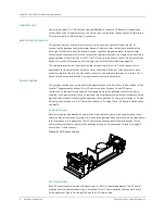
Cabinet Size and Clearance Requirements
A standard 19-in. (48.26 cm) cabinet can accommodate the gateway. A single gateway requires
1.5 RU of space in the cabinet.
In a cabinet, the space required in front of the gateway to accommodate the cables and cords is
different depending on which ports you use. 2.16 in. (5.5 cm) space is required on the front of the
gateway when you use the fiber-optic cables to connect the fiber-optic ports. However if you plan
to use only copper Ethernet ports, 1.57 in. (4 cm) space is sufficient on the front of the gateway.
Cabinet Airflow Requirements
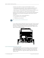
When you mount the gateway in a cabinet, you must ensure that ventilation through the cabinet is
sufficient to prevent overheating. Following is a list of requirements to consider when planning for
chassis cooling:
z
Ensure that the cabinet allows the chassis hot exhaust air to exit from the cabinet without
recirculating into the gateway. An open cabinet (without a top or doors) that employs hot air
exhaust extraction from the top allows the best airflow through the chassis. If the cabinet
contains a top or doors, perforations in these elements assist with removing the hot air exhaust.
z
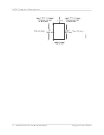
Ensure that you have at least 20 mm clearance behind the gateway in the rear of the cabinet for
free airflow (see Figure 13 on page 21).
z
Ensure that the gateway and all cables are dressed to minimize the blockage of airflow to and
from the chassis.
z
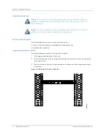
Ensure that there is a minimum of 3 in. (7.6 cm) clearance between the inner side wall and the
gateway for free air flow when the gateway is installed in a cabinet.
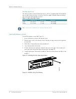
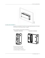
Clearance Requirements for Airflow and Hardware Maintenance
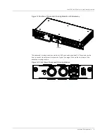
Plan the location of the gateway to provide space for connections to power, local communications,
and remote communications.
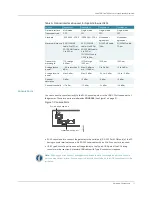
Allow 2.16 in. (5.5 cm) in front of the gateway for routing the cables
when the gateway is installed in a cabinet.
At least 6 in. (15.2 cm) of clearance is required between each side of the gateway and any
heat-producing equipment.
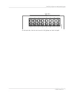
Figure 13: Chassis Dimensions and Clearance Requirements
Note:
Leave the front side of the gateway open for connecting the cables.
Summary of Contents for BX7000
Page 10: ... x Copyright 2010 Juniper Networks Inc ...
Page 12: ... xii Copyright 2010 Juniper Networks Inc ...
Page 18: ...About This Guide xviii Requesting Support Copyright 2010 Juniper Networks Inc ...
Page 20: ... 2 Copyright 2010 Juniper Networks Inc ...
Page 66: ... 48 Copyright 2010 Juniper Networks Inc ...
Page 90: ... 72 Copyright 2010 Juniper Networks Inc ...
Page 122: ... 104 Hardware Compliance Copyright 2010 Juniper Networks Inc ...
Page 131: ...Copyright 2010 Juniper Networks Inc 113 Appendix E Declaration of Conformity ...
Page 132: ... 114 Copyright 2010 Juniper Networks Inc ...
Page 133: ...Copyright 2011 Juniper Networks Inc 115 PART 4 Index z Index on page 117 ...

