background image

CHAPTER 5: Connecting the Gateway

34

Cabling the Gateway to Management and Alarm Devices

Copyright © 2010, Juniper Networks, Inc.

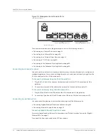
Figure 19:  Management and Console Ports

To connect external devices to the gateway ports, refer to the following sections:

z

Connecting to a Console Terminal on page 34

z

Connecting to an Ethernet Port on page 34

z

Connecting to an External Alarm Device on page 35

z

Connecting to T1/E1 Ports on page 36

z

Connecting to the Advanced Clocking Module on page 36

z

Connecting to the Advanced Clocking Module on page 36

Connecting to a Console Terminal 

Use a console terminal, such as a laptop, a desktop, or any other auxiliary device to configure and 

manage the gateway. You can connect the gateway to a console terminal directly using either the 

RJ-45 console port or the USB console ports.

To Connect the Gateway Using the RJ-45 Console Port: 

1.

Plug the RJ-45 end of the crossover twisted-pair cable into the RJ-45 console port of the 

gateway. 

2.

Connect the other end of the cable to the serial port of the console terminal or PC.

To Connect the Gateway Using the USB Console Port:

1.

Plug the Type B end of the USB cable to the USB console port of the gateway.

2.

Connect the Type A end of the USB cable to the USB port of the console terminal or PC. 

Connecting to an Ethernet Port

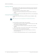
You can connect the gateway to external devices using any of the Ethernet ports. 

z

Connecting Gigabit Ethernet Fiber-Optic Cables on page 34

z

Connecting Ethernet Copper Cables on page 35

Connecting Gigabit Ethernet Fiber-Optic Cables

For more information about fiber-optic transceivers, see “Optical Interface Support for Gigabit 

Ethernet SFPs” on page 11.

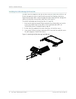
To connect the fiber-optic cable to the SFP transceivers:

USB console port

Copper Gigabit Ethernet ports

RJ-45 console port

Fiber-optic Gigabit Ethernet ports

CONSOLE

COPPER

COPPER

COPPER

SFP

SFP

ETHERNET 1

ETHERNET 1

ETHERNET 2

ETHERNET 2

ETHERNET 0

CONSOLE

g002909

Summary of Contents for BX7000

Page 1: ...nts of the University All rights reserved Gate Daemon was originated and developed through release 3 0 by Cornell University and its collaborators Gated is based on Kirton s EGP UC Berkeley s routing daemon routed and DCN s HELLO routing protocol Development of Gated has been supported in part by the National Science Foundation Portions of the GateD software copyright 1988 Regents of the Universit...

Page 2: ...552 918 6 567 902 6 578 186 and 6 590 785 BX7000 Multi Access Gateway Hardware Guide Copyright 2010 Juniper Networks Inc All rights reserved Printed in USA Revision History JAugust 2011 530 027514 01 Revision 1 0 The information in this document is current as of the date listed in the revision history Year 2000 Notice Juniper Networks hardware and software products are Year 2000 compliant The JUNO...

Page 3: ...f the Software Customer may operate the Software after the 30 day trial period only if Customer pays for a license to do so Customer may not extend or create an additional trial period by re installing the Software after the 30 day trial period e The Global Enterprise Edition of the Steel Belted Radius software may be used by Customer only to manage access to Customer s enterprise network Specific...

Page 4: ... to export the Software without an export license 12 Commercial Computer Software The Software is commercial computer software and is provided with restricted rights Use duplication or disclosure by the United States government is subject to restrictions set forth in this Agreement and as provided in DFARS 227 7201 through 227 7202 4 FAR 12 212 FAR 27 405 b 2 FAR 52 227 19 or FAR 52 227 14 ALT III...

Page 5: ...s 6 Ethernet Ports 8 Console Ports 11 USB Host Port 12 External Alarm Contacts 12 Power Supplies 12 Advanced Clocking Module 13 Location of Advanced Clocking Module in the Chassis 14 CHAPTER 2 Preparing the Site for Gateway Installation 19 Site Preparation Checklist 19 Wall Requirements 20 Rack Requirements 20 Rack Size and Strength 20 Proper Rack Installation 20 Cabinet Requirements 20 Cabinet Si...

Page 6: ...ering the Gateway 37 Tools and Parts Required 37 Connecting the Grounding Wire 37 Providing Power to the Gateway 39 Connecting Power to an AC Powered Gateway 39 Connecting Power to a DC Powered Gateway 39 Powering On the Gateway 40 Powering Off the Gateway 40 CHAPTER 7 Accessing and Configuring the Gateway 43 Console Port Setup 43 Initial Setup 44 Assigning an IP Address 44 SSH Setup 44 PART 2 Har...

Page 7: ... 75 Advanced Clocking Module Specifications 75 Power Guidelines Requirements and Specifications 76 Site Electrical Wiring Guidelines 76 Chassis Grounding Specifications 76 AC Power Specifications 77 AC Power Cord Specifications 77 DC Power Specifications 78 DC Power Cable Specifications 78 Appendix B Safety and Regulatory Compliance Information Definition of Safety Warning Levels 79 Safety Guideli...

Page 8: ...abling Details RJ 45 Connector Pinouts for RJ 45 Console Port 105 RJ 45 Connector Pinouts for Copper Ethernet Port 105 SFP Connector Pinouts for Fiber Optic Ethernet Port 106 RJ 45 Connector Pinouts for T1 E1 Port 106 Type B Connector Pinouts for USB Console Port 107 Type A Connector Pinouts for USB FLASH Port 107 RJ 45 Connector Pinouts for the BITS Interface 108 BNC Connector Pinouts 108 Appendi...

Page 9: ...sages 55 Table 18 Causes of Power Failures 56 Table 19 Field Replaceable Units 59 Table 20 Tools and Parts Required 60 Table 21 General Specifications 73 Table 22 Physical Specifications 75 Table 23 Gateway Environmental Specifications 75 Table 24 Advanced Clocking Module Specifications 75 Table 25 AC Power Supply Electrical Specifications 77 Table 26 AC Power Cord Specifications 77 Table 27 DC Po...

Page 10: ... x Copyright 2010 Juniper Networks Inc ...

Page 11: ... Bracket 28 Figure 15 Installing the Wall Mounting Bracket 30 Figure 16 Wall Mounting the Gateway 30 Figure 17 Rack Mounting Brackets for the Gateway 31 Figure 18 Rack Mounting the Gateway 32 Figure 19 Management and Console Ports 34 Figure 20 Connector for Ethernet Cable 35 Figure 21 Grounding Points on the Gateway 37 Figure 22 Attaching Grounding Wire to the Grounding Lug 39 Figure 23 Removing a...

Page 12: ... xii Copyright 2010 Juniper Networks Inc ...

Page 13: ...oting procedures for the BX7000 Multi Access Gateway It also explains how to prepare your site for the gateway installation unpack and install the hardware power on the gateway and perform routine maintenance After completing the installation procedures covered in this guide see the BXOS Configuration Guide for information about further BX operating system BXOS configuration Audience This guide is...

Page 14: ... screen cli BX7000 show chassis alarms No alarms currently active Italic typeface z Introduces important new terms z Identifies book names z Identifies RFC and Internet draft titles z A policy term is a named structure that defines match conditions and actions z BXOS Configuration Guide z RFC 1997 BGP Communities Attribute Italic sans serif typeface Represents variables options for which you subst...

Page 15: ...tion hierarchy level gateway Refers to BX7000 Multi Access Gateway Convention Description Examples Document Description BX7000 Multi Access Gateway Hardware Guide Provides a detailed hardware description of the gateway This guide z Explains how to unpack install mount access and maintain the gateway z Explains the various hardware components such as power supply chassis and ports z Provides troubl...

Page 16: ...juniper net customers support downloads 710059 pdf z Product warranties For product warranty information visit http www juniper net support warranty z JTAC Hours of Operation The JTAC centers have resources available 24 hours a day 7 days a week 365 days a year Self Help Online Tools and Resources For quick and easy problem resolution Juniper Networks has designed an online self service portal cal...

Page 17: ...nt tool in the CSC at http www juniper net cm z Call 1 888 314 JTAC 1 888 314 5822 toll free in the USA Canada and Mexico For international or direct dial options in countries without toll free numbers visit us at http www juniper net support requesting support html ...

Page 18: ...About This Guide xviii Requesting Support Copyright 2010 Juniper Networks Inc ...

Page 19: ...y Overview on page 3 z Preparing the Site for Gateway Installation on page 19 z Unpacking and Inspecting the Gateway on page 23 z Installing the Gateway on page 27 z Connecting the Gateway on page 33 z Grounding and Powering the Gateway on page 37 z Accessing and Configuring the Gateway on page 43 ...

Page 20: ... 2 Copyright 2010 Juniper Networks Inc ...

Page 21: ...r emulated circuits It allows simultaneous delivery of real time and delay tolerant traffic enhancing bandwidth utilization In addition it performs IPv4 forwarding Gateway System Architecture The gateway can be deployed at the cell sites base transceiver station BTS and access or aggregation hub for the cell sites The gateway architecture separates the control operations from the packet forwarding...

Page 22: ... concern routing protocols freeing the packet processor to handle only packets that transit through the system It also provides different levels of system configuration and management functions including command line interface CLI SNMP and a NETCONF interface Hardware Components This section provides the overview of the gateway s hardware components z Gateway Chassis on page 4 z Front Panel on pag...

Page 23: ...o view the status of the gateway and the ports and two slots for expansion see Figure 3 on page 5 Figure 3 Front Panel of the BX7000 Multi Access Gateway LEDs Port LEDs For more information on port LEDs see T1 E1 Ports on page 6 and Ethernet Ports on page 8 Table 1 Physical Specifications Description Value Chassis dimensions 2 6 in 6 7 cm high 17 51 in 44 47 cm wide 9 44 in 23 97 cm deep from fron...

Page 24: ...ed with an input source If the LED is amber the advanced clocking module is currently not locked and is either in holdover mode or free running mode Figure 4 LED in the Advanced Clocking Module T1 E1 Ports The T1 E1 ports provide connection to T1 or E1 network media types such as switches They receive incoming packets from the network and transmit outgoing packets to the network Figure 5 on page 6...

Page 25: ...ware Components 7 CHAPTER 1 BX7000 Multi Access Gateway Overview For information about the ports and connectors in the gateway see Table 3 on page 8 T1 E1 ports 0 2 4 6 8 10 12 14 1 3 5 7 9 11 13 15 g002940 ...

Page 26: ...Format z G 704 no crc Basic E1 framer format without CRC z Per port loop timing Software features z Integrated support for G 703 unframed mode and G 704 Channel Associated Signaling Multiframe Format and G 704 no crc z Encapsulations High Level Data Link Control HDLC Asynchronous Transfer Mode ATM Inverse Multiplexing over ATM ATM IMA Point to Point Protocol PPP Transparent Trans Cables and connec...

Page 27: ...RNET 2 you can connect both the copper Ethernet port and the fiber optic Ethernet port However only the copper port or the fiber optic port can be active at a time If both ports are connected the fiber optic port will be active You can also use combination of these ports as follows z ETHERNET 1 of copper Ethernet port and ETHERNET 2 of fiber optic Ethernet port z ETHERNET 2 of copper Ethernet port...

Page 28: ...lded twisted pair UTP Category 5e or 6 cable RJ 45 connector z Use Category 5e UTP cables for copper Ethernet ports if the installation environment requires radiated noise immunity 3 V m conducted noise immunity 3 V z Use Category 5e shielded twisted pair STP cables for copper Ethernet ports if the installation environment requires radiated noise immunity 3 V m conducted noise immunity 3 V z SFP F...

Page 29: ...ical interface Multimode Single mode Single mode Single mode Transceiver type SFP SFP SFP SFP Standard IEEE 802 3 2005 IEEE 802 3 2005 Multivendor agreement Multivendor agreement Maximum distance 62 5 125 MMF cable 2 to 220 m 50 125 MMF cable 2 to 550 m 62 5 125 MMF cable 2 to 550 m 50 125 MMF cable 2 to 550 m 10 125 SMF cable 0 002 to 5 km 9 125 SMF cable 10 km 9 125 SMF cable 70 km Transmitter w...

Page 30: ...alarm device A total of four devices may be connected to the wire trap connector using the eight pins Power Supplies The gateway contains one or two power supplies located on the left side of the front panel of the chassis The gateway uses either AC or DC power supplies For both AC and DC power configurations the power supplies are hot swappable when the gateway contains two power supplies If one ...

Page 31: ...iming Externally available reference clocks are BITS T1 E1 rate clocks 1 PPS and 10 MHz The two BNC connectors and one RJ 45 port on the front panel of the advanced clocking module connect to external clock signal sources The advanced clocking module provides the synchronized output clocks from any one of the above reference inputs based on the clock s priority There are eight methods to acquire a...

Page 32: ...ations z ITU T G 823 G 824 for E1 T1 clock requirements z PTP IEEE1588 support for slave mode You can configure the priority of the available clock sources from 1 through 7 The clock source with priority one is locked and distributed to the TDM interfaces of the gateway As the port providing the clock source might fail the priority for reference clock sources is programmable For more information a...

Page 33: ...anced Clocking Module on the Gateway The advanced clocking module contains two BNC connectors and one RJ 45 connector on the front to connect the external clock sources Figure 12 on page 15 shows the front view of the advanced clocking module Figure 12 Front View of Advanced Clocking Module Clock Card ...

Page 34: ...048MHz line clocks Ethernet recovered clocks IEEE1588V2 recovered clock xDSL NTU R timing External BITS T1 E1 1 544 2 048 MHz through RJ 45 Cat 3 10 MHz LVCMOS through BNC connectors 50 ohms TTL z Provides synchronized reference clock outputs Internal T1 E1 1 544 2 048 MHz line clocks to mother board and daughter board 25 MHz clock to Ethernet interface in mother board and daughter board 8 192 MHz...

Page 35: ...ous source z Alarm and status retrieval using CLI commands z ACS 9510 firmware upgraded through a BXOS application z Manual control to switch to or from PTP source PTP highest priority z Polling of PTP alarm point to indicate when to switch to or from PTP source z PTP synchronization signal not monitored before switching to it z Alarm raised polling when no more wired sources can be selected Table...

Page 36: ...CHAPTER 1 BX7000 Multi Access Gateway Overview 18 Advanced Clocking Module Copyright 2010 Juniper Networks Inc ...

Page 37: ... the gateway The checklist in Table 10 on page 19 summarizes the tasks you need to perform when preparing a site for gateway installation Table 10 Site Preparation Checklist Item or Task For More Information Performed By Date Verify that environmental conditions such as temperature and humidity do not exceed gateway tolerance Gateway Environmental Specifications on page 75 If mounting in a rack se...

Page 38: ...y 1 5 RU The chassis comes with brackets for use with the 19 in rack Prepare the equipment racks by measuring and marking the space for each gateway you plan to install Proper Rack Installation To confirm proper equipment rack installation verify the following z Racks are installed and electrically grounded according to manufacturer instructions z Always secure the rack to the structure of the bui...

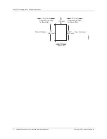
Page 39: ...into the gateway An open cabinet without a top or doors that employs hot air exhaust extraction from the top allows the best airflow through the chassis If the cabinet contains a top or doors perforations in these elements assist with removing the hot air exhaust z Ensure that you have at least 20 mm clearance behind the gateway in the rear of the cabinet for free airflow see Figure 13 on page 21 ...

Page 40: ... Requirements for Airflow and Hardware Maintenance Copyright 2010 Juniper Networks Inc 17 51 44 4 cm Rear of chassis 19 48 3 cm 3 7 6 cm 2 16 5 5 cm Clearance required for the cables 0 75 2 cm Clearance required for free airflow Front of chassis g002903 9 44 23 97 cm ...

Page 41: ... The box measures 4 72 in 12 cm high 14 17 in 36 cm wide and 22 83 in 58 cm deep The box weighs 18 07 lb 8 2 Kg A Getting Started Guide is also included in each box To unpack the gateway 1 Open the box cover with a knife 2 Remove the chassis shipping kit and Getting Started Guide from the box 3 Remove the ESD bag that covers the gateway 4 Save the box cover and packing materials in case you need t...

Page 42: ...of a wall mounting kit are listed in Table 13 on page 24 23 inch Rack Mounting Kit You can order a 23 inch rack mounting kit The parts of a 23 inch rack mounting kit are listed in Table 14 on page 24 Part Quantity 19 in mounting brackets 2 Product warranty 1 Getting Started Guide 1 Cable management brackets 2 EULA 1 Table 12 Installation Kit Contents Part Quantity 1 GB USB flash drive 1 USB consol...

Page 43: ...ontact the shipper responsible for delivery and formally report the damage z Contact Juniper Networks at 1 888 314 JTAC from the United States Canada or Mexico or 1 408 745 9500 from elsewhere or contact your sales representative if you have any questions or concerns See Contacting Customer Support and Returning Hardware on page 109 for complete contact information ...

Page 44: ...CHAPTER 3 Unpacking and Inspecting the Gateway 26 If You Detect or Suspect Damage Copyright 2010 Juniper Networks Inc ...

Page 45: ...arnings see Safety and Regulatory Compliance Information on page 79 and particularly Safety and Regulatory Compliance Information on page 79 However providing an exhaustive set of guidelines for working with electrical equipment is beyond the scope of this guide Before you Begin Before installing the gateway ensure the following z Verify that you have prepared the installation site as described in...

Page 46: ...ed to undue stress at the connector To install the cable management bracket see Figure 14 on page 28 1 Attach an electrostatic discharge ESD grounding strap to your bare wrist and connect the strap to one of the ESD points on the chassis For more information about ESD see Preventing Electrostatic Discharge Damage on page 83 2 Position the cable management bracket into the slots on the front of the...

Page 47: ...age 29 z Installing the Gateway on a Wall on page 30 Tools and Parts Required To install the gateway on a wall you need the following tools z An appropriate screwdriver z Three mounting screws ST 3 5 X 25 supplied with the wall mounting kit z Powered drill z Three nylon plugs 5 X 25 supplied with the wall mounting kit z Wall mounting bracket supplied with the wall mounting kit For more information...

Page 48: ...an to drive the nail using the wall mounting bracket as a template 3 Make holes in the marked points using a powered drill 4 Insert the plug into the holes made 5 Position the wall mounting bracket and place the screws in the plugs Use a screwdriver to secure them at all three mounting points see Figure 15 on page 30 6 Hang the gateway on the two studs provided on the wall mounting bracket see Fig...

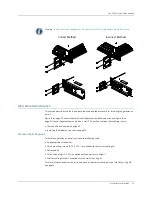
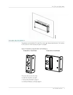
Page 49: ...propriate brackets The brackets for 19 in and 23 in racks are shown in Figure 17 on page 31 Figure 17 Rack Mounting Brackets for the Gateway This section describes the following z Installation Guidelines on page 32 z Tools and Parts Required on page 32 z Installing the Gateway in a Rack on page 32 g002906 Bracket for 19 inch Rack Bracket for 23 inch Rack ...

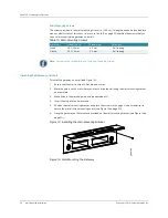
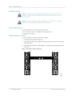
Page 50: ... it in the rack 2 Ensure that the holes of the mounting brackets align evenly with the holes of the equipment rack on both sides 3 Place the screws in the holes of the equipment rack and secure them using an appropriate screwdriver Figure 18 Rack Mounting the Gateway Warning Do not install more than three gateways adjacently in the same rack This avoids excessive pre heating of the air flowing thr...

Page 51: ...e ports see BX7000 Multi Access Gateway Overview on page 3 2 Consider the distance from the connection points such as power communication and the place of installing the gateway when determining the size of cables and wires to be used To familiarize yourself with the electrical environmental and other guidelines and requirements see Safety Guidelines and Warnings on page 80 3 Use the cable managem...

Page 52: ...ort 1 Plug the RJ 45 end of the crossover twisted pair cable into the RJ 45 console port of the gateway 2 Connect the other end of the cable to the serial port of the console terminal or PC To Connect the Gateway Using the USB Console Port 1 Plug the Type B end of the USB cable to the USB console port of the gateway 2 Connect the Type A end of the USB cable to the USB port of the console terminal ...

Page 53: ...he front panel A condition that triggers the red or yellow alarm LED on the front panel also activates the corresponding alarm relay contact The alarm relay contacts accept wire of any gauge between 26 AWG and 24 AWG 0 4 to 0 5 mm2 To connect an external device to the alarm relay contact 1 Prepare the required length of single core wire with gauge of 26 AWG or 24 AWG 2 Insert wires into the first ...

Page 54: ...ced Clocking Module You can use either of the two BNC connectors or the BITS interface on the advanced clocking module To connect the BNC co axial cable to the advanced clocking module 1 Connect one end of the BNC co axial cable to either the 1PPS BNC connector or the 10 MHz BNC connector on the advanced clocking module 2 Connect the other end of the BNC co axial cable to the 10 MHz or 1PPS source...

Page 55: ...round wire Use 14 AWG to10 AWG copper wire z Power cord For more information on the power cord see AC Power Cord Specifications on page 77 z Power cable For more information on power cables see DC Power Cable Specifications on page 78 Connecting the Grounding Wire Ground the gateway by connecting a grounding wire to earth ground and then connecting the other end to one of the chassis grounding poi...

Page 56: ...of the grounding wire into the open end of the 5 8 pitch twin hole grounding lug and crimp the grounding wire securely to the lug see Figure 22 on page 39 Use the lug manufacturer s recommended crimping tool to ensure a proper crimp 7 Attach the grounding lug to the threaded holes on the chassis and secure them first with washers and then with M4 size nut 8 Connect the other end of the grounding w...

Page 57: ...rist and connect the strap to one of the ESD points on the chassis For more information about ESD see Preventing Electrostatic Discharge Damage on page 83 3 Insert the appliance coupler end of the power cord into the power supply receptacle in the gateway 4 Insert the power cord plug into an AC power source receptacle 5 Repeat Steps 1 through 4 for the other power supply Connecting Power to a DC P...

Page 58: ...e chassis 4 Verify that the source power cord is securely inserted into the appliance inlet 5 Switch on the customer site circuit breakers to provide voltage to the power supply When the gateway is powered on successfully and diagnostic tests are complete the system LED is lit green indicating that the gateway and power supplies are functioning normally See System LED on page 6 6 Monitor the start...

Page 59: ... To discard the configuration type no Depending on the input the gateway either reboots after saving the previous configurations or reboots without saving For more information about the command see the BXOS CLI Users Guide and Command Reference 2 Follow your site instructions to turn off the power to the gateway ...

Page 60: ...CHAPTER 6 Grounding and Powering the Gateway 42 Powering Off the Gateway Copyright 2010 Juniper Networks Inc ...

Page 61: ...Microsoft Windows Macintosh or UNIX workstation You can use any terminal application to communicate with the gateway The following settings are required for the terminal emulation program z Baud rate 9600 z Data bits 8 z Parity None z Stop bits 1 z Flow control None After you power on the gateway your console is ready to communicate with the gateway The gateway performs the bootup process and disp...

Page 62: ...figured an IP address for the system you can run the SSH client from a host to access the gateway through its configured port SSH enables remote systems to establish a secure connection with the gateway The gateway supports implementation of both the SSH server and the client The SSH server functionality enables remote hosts having the SSH client functionality to log on securely to the gateway The...

Page 63: ... CHAPTER 7 Accessing and Configuring the Gateway Caution Do not change the IP address for the Ethernet interface that you are using to communicate with the system If you change the address you will lose the SSH session ...

Page 64: ...CHAPTER 7 Accessing and Configuring the Gateway 46 Initial Setup Copyright 2010 Juniper Networks Inc ...

Page 65: ...t 2011 Juniper Networks Inc 47 PART 2 Hardware Maintenance Troubleshooting and Replacement Procedures z Maintaining the Gateway on page 49 z Troubleshooting on page 53 z Replacing Hardware Components on page 59 ...

Page 66: ... 48 Copyright 2010 Juniper Networks Inc ...

Page 67: ...verview on page 3 z Periodically inspect the site to ensure that the grounding and the power cords connected to the gateway are securely in place and that there is no moisture accumulating near the gateway Maintaining Cables To maintain cables z Use the cable management brackets to support cables and prevent cables from dislodging or developing stress points z Place excess cable out of the way in ...

Page 68: ...ou have cleaned the transceiver on the fiber optic port make sure that the connector tip of the fiber optic cable is clean Use only an approved alcohol free fiber optic cable cleaning kit such as the Opptex Cletop S Fiber Cleaner Follow the directions for the cleaning kit you use Maintaining Power Supplies To maintain the power supplies z Check the status of the power supplies by issuing the show ...

Page 69: ...ck First Priority Validated Source bits clock Second Priority Validated Source none Third Priority Validated Source none z Use the show clock card status command to check the status of the input and output clocks As shown in the sample output the value corresponding to priority field indicates the priority set for the input clock the validity field indicates the status of the clock that is valid a...

Page 70: ...2010 Juniper Networks Inc Second Highest Priority Validated Source none Third Highest Priority Validated Source none Output Clock Status Internal output clocks Ethrnet clock enable 8 Khz Sync enable 19 44 Diff clock enable T1 E1 TDM Clock enable External output clocks one pps clock enable ...

Page 71: ... 2 Observe the gateway LEDs carefully 3 Make sure cable connections on the gateway are securely connected 4 Ensure that the expansion cards and advanced clocking module are properly installed in the chassis If a problem is beyond the scope of this chapter see Contacting Customer Support and Returning Hardware on page 109 for further instructions Understanding the Status LEDs to Troubleshoot LEDs s...

Page 72: ...cal condition that can cause the gateway to stop functioning Yellow indicates a non critical or minor condition that requires monitoring For more information see System LED on page 54 Chassis and Interface Alarm Messages When the gateway detects an alarm condition it lights the red or the yellow alarm LED To view a more detailed description of the cause for the alarm issue the show chassis alarms ...

Page 73: ...attention z If the system LED is off and no red alarm condition exists check if the gateway is connected to a power supply z Verify that the power cords from the power source to the gateway are not damaged Replace the cable if the insulation is cracked or broken z Connect the power supply to a different power source with a new power cable If the system LED still does not light the power supply inl...

Page 74: ...chassis environment command z Use the show chassis environment command to check the temperature and the status of the power supply in the gateway As shown in the sample output the value Current Temperature corresponding to the Temperature field indicates the temperature of the gateway cli BX7000 show chassis environment Power Instance 0 Power_status ON Instance 1 Power_status ON Symptom Possible p...

Page 75: ... 0 0 1 RED 2000 01 01 00 02 00 UTC Other e1 0 0 1 Loss of Frame 2000 01 01 00 01 55 UTC Other e1 0 0 0 Alarm Indication Signal 2000 01 01 00 02 00 UTC Other e1 0 0 1 Loss of Signal 2000 01 01 00 01 48 UTC Other gige 1 0 1 Link Down Troubleshooting the Advanced Clocking Module If the card is not inserted properly in the Clock Card Expansion Bay slot the POST displays the error message card is not d...

Page 76: ...CHAPTER 9 Troubleshooting 58 Troubleshooting the Advanced Clocking Module Copyright 2010 Juniper Networks Inc ...

Page 77: ...lacing the Fuse on page 64 z Replacing SFP Transceivers on page 65 z Replacing Alarm Relay Wires on page 67 z Replacing the Advanced Clocking Module on page 68 z Replacing the Advanced Clocking Module on page 68 z Replacing the Advanced Clocking Module on page 68 Field Replaceable Units Field replaceable units FRUs are components that can be replaced at the customer site The gateway uses the follo...

Page 78: ...tatic discharge ESD grounding strap to your bare wrist and connect the strap to the ESD point on the chassis For more information about ESD see Preventing Electrostatic Discharge Damage on page 83 3 Unplug the power cord from the AC receptacle on the power supply 4 Loosen the thumbscrews at the top corners of the power supply 5 Grasp the handle on the power supply faceplate and pull the power supp...

Page 79: ...es are located at the front of the chassis Each DC power supply weighs approximately 0 71 lb 0 32 kg For more information about DC power supply specifications see Table 27 on page 78 To replace a DC power supply perform the following procedures z Removing a DC Power Supply on page 61 z Installing a DC Power Supply on page 62 Removing a DC Power Supply To remove a DC power supply see Figure 25 on p...

Page 80: ...harge ESD grounding strap to your bare wrist and connect the strap to the ESD point on the chassis For more information about ESD see Preventing Electrostatic Discharge Damage on page 83 3 Slide the power supply straight into the chassis until the power supply is fully seated in the chassis 4 Tighten but do not overtighten the thumbscrews located at the top corners of the power supply 5 Remove the...

Page 81: ...e power supply Connecting an AC Power Cord To connect the AC power cord 1 Locate a replacement power cord with the type of plug appropriate for your geographical location see AC Power Cord Specifications on page 77 2 Connect one end of the power cord to the power supply 3 Insert the power cord plug into an external AC power source receptacle 4 Ensure that the power cord does not block the access t...

Page 82: ...cement power cable 3 Make sure that the voltage across the DC power source cable leads is 0 V and that there is no chance that the cables might become active during the removal process 4 Secure the power cable lug to the terminal studs 5 Make sure the cable is not touching or in the way of the gateway and that it does not drape where people could trip on it 6 Attach the power cable to the DC power...

Page 83: ...factor pluggable transceivers SFPs on the front panel SFPs are hot insertable and hot removable see Figure 28 on page 65 but the fiber optic ports no longer receive or transmit data during replacement Figure 28 SFP Connector Caution For continued protection against risk of fire replace only with same type and rating of fuse ATTENTION Pour ne pas compromettre la protection contre les risques d ince...

Page 84: ...lace a rubber safety cap over the SFP Installing an SFP To install an SFP see Figure 38 on page 85 1 Identify the slot where the SFP will be installed 2 Verify that each SFP is covered by a rubber safety cap If it is not cover the SFP with a safety cap 3 Carefully align the SFP with the SFP slots The connectors should face the SFP slot 4 Slide the SFP until the SFP connector is seated in the SFP s...

Page 85: ...ame Figure 29 Installing an SFP Replacing Alarm Relay Wires To replace the wires connected to an external alarm device see Figure 30 on page 67 1 Disconnect the existing wire at the external device 2 Prepare the required length of replacement wire 3 Using a screwdriver push the body cover of the connector located on the top of the wire which is to be disconnected from the wire trap connector 4 Rem...

Page 86: ...ing the Advanced Clocking Module on page 68 z Installing the Advanced Clocking Module on page 69 Removing the Advanced Clocking Module To remove the advanced clocking module see Figure 31 on page 68 1 Attach an ESD wrist strap to your bare wrist and connect the wrist strap to one of the ESD points on the chassis 2 Switch off the dedicated customer site circuit breakers before disconnecting the pow...

Page 87: ...that covers the slot 5 Remove the peel off paper from the thermal pad of the advanced clocking module 6 Hold the advanced clocking module horizontally with the BITS interface and BNC connectors facing towards you and the connectors facing the chassis slot 7 Horizontally align the card with the guides at the right and left of the slot 8 Gently push the card into the slot until the card is fully sea...

Page 88: ...CHAPTER 10 Replacing Hardware Components 70 Replacing the Advanced Clocking Module Copyright 2010 Juniper Networks Inc ...

Page 89: ...RT 3 Appendices z System Specifications on page 73 z Safety and Regulatory Compliance Information on page 79 z Cabling Details on page 105 z Contacting Customer Support and Returning Hardware on page 109 z Declaration of Conformity on page 113 ...

Page 90: ... 72 Copyright 2010 Juniper Networks Inc ...

Page 91: ...del 13 38 lb 6 07 kg Dimensions 17 5 x 2 6 x 9 4 in 44 5 x 6 7 x 24 cm Environmental Requirements Ambient operating temperature Ambient operating humidity Ambient storage temperature Ambient storage humidity NEBS GR 63 CORE compliant NEBS GR 1089 CORE compliant z DC Hardened 40 to 158 F 40 to 70 C z DC Non hardened 23 to 131 F 5 to 55 C z AC 23 to 131 F 5 to 55 C 95 maximum noncondensing 40 to 70 ...

Page 92: ... EN60825 1 Safety of Laser Products Part 1 Equipment Class Requirements and User s Guide z EN 60950 1 2006 Information Technology Equipment Safety Part 1 General Requirements z IEC 60950 1 CB Scheme Telecommunications Certification z T1 interfaces FCC ACTA TIA EIA IS 968 Covers all types of terminal equipment for direct connection to the public switched network Includes both digital and analog int...

Page 93: ...figured Chassis with dual power supply fully configured 12 23 lb 5 54 kg 12 94 lb 5 87 kg Weight AC model Chassis with single power supply fully configured Chassis with dual power supply fully configured 12 45 lb 5 65 kg 13 38 lb 6 07 kg Table 23 Gateway Environmental Specifications Description Value Relative humidity Normal operation ensured in relative humidity range of 5 to 95 noncondensing Tem...

Page 94: ...licable Electromagnetic Compatibility If your site is susceptible to problems with electromagnetic compatibility EMC particularly from lightning or radio transmitters you might want to seek expert advice Strong sources of electromagnetic interference EMI can destroy the signal drivers and receivers in the gateway and conduct power surges over the lines into the equipment resulting in an electrical...

Page 95: ... on page 77 depicts the plug types for AC power cord provided for each country Figure 33 AC Plug Types For information about the AC power supply see AC Power Supply on page 12 For instructions on connecting the power cord and grounding cable during initial installation see Connecting the Grounding Wire on page 37 and Providing Power to the Gateway on page 39 Table 25 AC Power Supply Electrical Spe...

Page 96: ... rating of at least 10 amperes You can use a spade lug of size 4 to attach the DC power cable to the terminal stud Table 28 on page 78 summarizes the specifications for the power cables which you must supply Table 27 DC Power Supply Electrical Specifications Item Description Maximum output power for each power supply 50 W DC input voltage 24V to 60V DC Maximum DC output voltage 12V Maximum DC outp...

Page 97: ...helpful in a particular situation or might otherwise overlook it Caution You need to observe the specified guidelines to avoid minor injury or discomfort to you or severe damage to the gateway Warning This symbol means danger You are in a situation that could cause physical injury Before you work on any equipment be aware of the hazards involved with electrical circuitry and be familiar with stand...

Page 98: ...n die zu einer Körperverletzung führen könnte Bevor Sie mit der Arbeit an irgendeinem Gerät beginnen seien Sie sich der mit elektrischen Stromkreisen verbundenen Gefahren und der Standardpraktiken zur Vermeidung von Unfällen bewußt Avvertenza Questo simbolo di avvertenza indica un pericolo La situazione potrebbe causare infortuni alle persone Prima di lavorare su qualsiasi apparecchiatura occorre ...

Page 99: ...bject that is too heavy for one person to handle z Never install or manipulate wiring during electrical storms z Operate the gateway only when it is properly grounded z Replace fuses only with fuses of the same type and rating Exercise the following guidelines to prevent electric shock fire and damage to the gateway z Do not open or remove chassis covers or sheet metal parts unless instructions ar...

Page 100: ... qualifié et compétent Warnung Gerät nur von geschultem qualifiziertem Personal installieren oder auswechseln lassen Avvertenza Solo personale addestrato e qualificato deve essere autorizzato ad installare o sostituire questo apparecchio Advarsel Kun kvalifisert personell med riktig opplæring bør montere eller bytte ut dette utstyret Aviso Este equipamento deverá ser instalado ou substituído apena...

Page 101: ...autre moyen de sécurité L accès aux zones de sécurité est sous le contrôle de l autorité responsable de l emplacement Warnung Diese Einheit ist zur Installation in Bereichen mit beschränktem Zutritt vorgesehen Ein Bereich mit beschränktem Zutritt ist ein Bereich zu dem nur Wartungspersonal mit einem Spezialwerkzeugs Schloß und Schlüssel oder anderer Sicherheitsvorkehrungen Zugang hat und der von d...

Page 102: ...tinguishers which use noncorrosive fire retardants such as carbon dioxide CO2 and Halotron are most effective for suppressing electrical fires Type C fire extinguishers displace the oxygen from the point of combustion to eliminate the fire For extinguishing fire on or around equipment that draws air from the environment for cooling you should use this type of inert oxygen displacement extinguisher...

Page 103: ...den Aviso Leia as instruções de instalação antes de ligar o sistema à sua fonte de energia Atención Ver las instrucciones de instalación antes de conectar el sistema a la red de alimentación Varning Läs installationsanvisningarna innan du kopplar systemet till dess strömförsörjningsenhet Warning To prevent physical injury when mounting or servicing the gateway in a rack ensure that the gateway is ...

Page 104: ... to unknown sources z Do not examine unterminated optical ports with optical instruments z Avoid direct exposure to the beam Class 1 Laser Product Warning Warning Unterminated optical connectors can emit invisible laser radiation The lens in the human eye focuses all the laser power on the retina so focusing the eye directly on a laser source even a low power laser could permanently damage the eye...

Page 105: ... rechtstreeks bekijken met optische instrumenten Varoitus Älä katso säteeseen äläkä tarkastele sitä suoraan optisen laitteen avulla Attention Ne pas fixer le faisceau des yeux ni l observer directement à l aide d instruments optiques Warnung Nicht direkt in den Strahl blicken und ihn nicht direkt mit optischen Geräten prüfen Avvertenza Non fissare il raggio con gli occhi né usare strumenti ottici ...

Page 106: ...l est recommandé de ne pas regarder fixement l intérieur de ces ouvertures Warnung Aus der Port Öffnung können unsichtbare Strahlen emittieren wenn kein Glasfaserkabel angeschlossen ist Vermeiden Sie es sich den Strahlungen auszusetzen und starren Sie nicht in die Öffnungen Avvertenza Quando i cavi in fibra non sono inseriti radiazioni invisibili possono essere emesse attraverso l apertura della p...

Page 107: ...nd die Erde angeschlossen werden und können schwere Verbrennungen verursachen oder an die Anschlußklemmen angeschweißt werden Avvertenza Prima di intervenire su apparecchiature collegate alle linee di alimentazione togliersi qualsiasi monile inclusi anelli collane braccialetti ed orologi Gli oggetti metallici si riscaldano quando sono collegati tra punti di alimentazione e massa possono causare us...

Page 108: ... e desligue cabos durante períodos de mau tempo trovoada Atención No operar el sistema ni conectar o desconectar cables durante el transcurso de descargas eléctricas en la atmósfera Varning Vid åska skall du aldrig utföra arbete på systemet eller ansluta eller koppla loss kablar Warning To prevent the gateway from overheating do not operate it in an area that exceeds the maximum recommended ambien...

Page 109: ...i Juniper Networks router Disse skal ikke brukes på steder der den anbefalte maksimale omgivelsestemperaturen overstiger 40 C 104 F Sørg for at klaringen rundt lufteåpningene er minst 15 2 cm 6 tommer for å forhindre nedsatt luftsirkulasjon Aviso Para evitar o sobreaquecimento do encaminhador Juniper Networks router não utilize este equipamento numa área que exceda a temperatura máxima recomendada...

Page 110: ...es National Fire Protection Association NFPA 70 United States National Electrical Code z Canada Canadian Electrical Code Part 1 CSA C22 1 Warning Disposal of this product must be handled according to all national laws and regulations Waarschuwing Dit produkt dient volgens alle landelijke wetten en voorschriften te worden afgedankt Varoitus Tämän tuotteen lopullisesta hävittämisestä tulee huolehtia...

Page 111: ...teway is connected to earth ground during normal use Waarschuwing Deze apparatuur hoort geaard te worden Zorg dat de host computer tijdens normaal gebruik met aarde is verbonden Varoitus Tämä laitteisto on tarkoitettu maadoitettavaksi Varmista että isäntälaite on yhdistetty maahan normaalikäytön aikana Attention Cet équipement doit être relié à la terre S assurer que l appareil hôte est relié à la...

Page 112: ...se Einheit verfügt über mehr als einen Stromanschluß um Strom gänzlich von der Einheit fernzuhalten müssen alle Stromzufuhren abgetrennt sein Avvertenza Questa unità ha più di una connessione per alimentatore elettrico tutte le connessioni devono essere completamente rimosse per togliere l elettricità dall unità Advarsel Denne enheten har mer enn én strømtilkobling Alle tilkoblinger må kobles helt...

Page 113: ...ab bzw schalten Sie bei Gleichstromeinheiten den Strom am Unterbrecher ab Avvertenza Prima di lavorare su un telaio o intorno ad alimentatori scollegare il cavo di alimentazione sulle unità CA scollegare l alimentazione all interruttore automatico sulle unità CC Advarsel Før det utføres arbeid på kabinettet eller det arbeides i nærheten av strømforsyningsenheter skal strømledningen trekkes ut p ve...

Page 114: ...ments and Warning on page 98 z DC Power Wiring Terminations Warning on page 98 DC Power Electrical Safety Guidelines The following electrical safety guidelines apply to a DC powered gateway z A DC powered gateway is equipped with a DC terminal block that is rated for the power requirements of a maximally configured gateway z A DC powered gateway that is equipped with a DC terminal block is intende...

Page 115: ...piirissä ei ole virtaa ennen seuraavien toimenpiteiden suorittamista Varmistaaksesi että virta on KATKAISTU täysin paikanna tasavirrasta huolehtivassa kojetaulussa sijaitseva suojakytkin käännä suojakytkin KATKAISTU asentoon ja teippaa suojakytkimen varsi niin että se pysyy KATKAISTU asennossa Attention Avant de pratiquer l une quelconque des procédures ci dessous vérifier que le circuit en couran...

Page 116: ...rsörjning är BRUTEN genom att slå AV det överspänningsskydd som skyddar likströmskretsen och tejpa fast överspänningsskyddets omkopplare i FRÅN läget Warning When installing the gateway the ground connection must always be made first and disconnected last Waarschuwing Bij de installatie van het toestel moet de aardverbinding altijd het eerste worden gemaakt en het laatste worden losgemaakt Varoitu...

Page 117: ...1000 3 2 Power Line Harmonics z Immunity z EN 61000 3 3 Voltage Fluctuations and Flicker z EN 61000 4 2 ESD z EN 61000 4 3 Radiated Immunity z EN 61000 4 4 EFT z EN 61000 4 5 Surge z EN 61000 4 6 Low Frequency Conducted Immunity z EN 61000 4 11 Voltage Dips and Sags z Deutsche Telecom 1TR9 EMC requirements z British Telecom Mobile Immunity Requirements z ETSI z ETSI EN 300 386 Telecommunication Ne...

Page 118: ...ect the interference at his own expense Compliance Statements for Environmental Requirements Lithium Battery Batteries in this product are not based on mercury lead or cadmium substances The batteries used in this product are in compliance with EU Directives 91 157 EEC 93 86 EEC and 98 101 EEC The product documentation includes instructional information on the proper method of reclamation and recy...

Page 119: ...se the user will be required to correct the interference at his own expense This equipment is designed for use with properly shielded and terminated cables Refer to the installation sections of this manual before operation FCC Requirements for Consumer Products This equipment complies with FCC rules ACTA TIA EIA IS 968 On the back side of this equipment is a label that contains among other informa...

Page 120: ...tifié c est à dire qu il respecte certaines exigences de sécurité et de fonctionnement visant les réseaux de télécommunications Le ministère ne garantit pas que l appareillage fonctionnera à la satisfaction de l utilisateur Avant d installer l appareillage s assurer qu il peut être branché aux installations du service de télécommunications local L appareillage doit aussi être raccordé selon des mé...

Page 121: ...talled using an acceptable method of connection In some cases the company s inside wiring associated with a single line individual service may be extended by means of a certified connector assembly telephone extension cord The customer should be aware that compliance with the above condition may not prevent degradation of service in some situations Repairs to certified equipment should be made by ...

Page 122: ... 104 Hardware Compliance Copyright 2010 Juniper Networks Inc ...

Page 123: ... The console port on the front panel labeled CONSOLE is an RJ 45 console interface that accepts an RJ 45 end cable for connecting the gateway to a console management device RJ 45 Connector Pinouts for Copper Ethernet Port The copper ports labeled COPPER and ETHERNET are autosensing 10 100 Mbps Ethernet RJ 45 receptacles that accept shielded or unshielded twisted pair UTP cable as required for conn...

Page 124: ...ccept an RJ 45 connector for connecting the gateway to T1 E1 ports in a network 2 BI_DA 3 BI_DB 4 BI_DC 5 BI_DC 6 BI_DB 7 BI_DD 8 BI_DD Table 30 RJ 45 Connector Pinouts for Ethernet Port RJ 45 Pin 1000Base T Signal Table 31 SFP Connector Pinouts for Fiber Optic Ethernet Port Pin number Signal 1 VeeT 2 TX Fault 3 TX Disable 4 MOD DEF2 5 MOD DEF1 6 MOD DEF0 7 Rate Select 8 LOS 9 VeeR 10 VeeR 11 VeeR...

Page 125: ... gateway to a management console The ports are configured as data terminal equipment DTE Type A Connector Pinouts for USB FLASH Port The USB port on the front panel labeled FLASH is a Type A receptacle that connect to any memory stick or auxiliary unit 4 TX Tip 5 TX Ring 6 No Connect 7 No Connect 8 No Connect Table 32 RJ 45 Connector Pinouts for T1 E1 Port RJ 45 Pin Signal Table 33 USB Type B Conn...

Page 126: ... pinouts for the RJ 45 connector BNC Connector Pinouts Table 36 on page 108 lists connector pinouts for the BNC connectors Table 34 USB Type A Connector Pinouts Pin Signal 1 5 2 Data 3 Data 4 GND Table 35 RJ 45 Connector Pinouts for BITS Interface Pin Signal 1 RX Tip 2 RX Ring 3 No Connect 4 No Connect 5 No Connect 6 No Connect Table 36 BNC Connector Pinouts Pin Signal 1 Center core Signal 2 Outer...

Page 127: ...uniper net support guidelines html Locating Serial Numbers Before contacting Juniper Networks Inc to request a Return Materials Authorization RMA you must find the serial number on the gateway or component see Figure 34 on page 110 To list the gateway serial number issue the following command line interface CLI command cli BX7000 show chassis hardware Hw name BX 7000 revision 02 serial D0000 H9999...

Page 128: ...er JTAC in one of the following ways You can contact JTAC 24 hours a day seven days a week z On the Web using the Case Manager link at http www juniper net support z By telephone From the US and Canada 1 888 314 JTAC From all other locations 1 408 745 9500 If contacting JTAC by phone enter your 11 digit case number followed by the key if this is an existing case or press the key to be routed to th...

Page 129: ... Contacting Customer Support on page 110 3 Provide the following information in your e mail message or during the telephone call z Part number and serial number of component z Your name organization name telephone number and fax number z Description of the failure 4 The support representative validates your request and issues an RMA number for return of the component 5 Pack the gateway or componen...

Page 130: ... use comparable shipping material or contact your Juniper Networks representative for information on approved packaging material To pack the chassis for shipment follow these guidelines z Remove all cables from the chassis z Remove the chassis from the rack and place the gateway in the box to be shipped z Cover the chassis with packing foam on top of the chassis z Securely tape the closed box z Wr...

Page 131: ...Copyright 2010 Juniper Networks Inc 113 Appendix E Declaration of Conformity ...

Page 132: ... 114 Copyright 2010 Juniper Networks Inc ...

Page 133: ...Copyright 2011 Juniper Networks Inc 115 PART 4 Index z Index on page 117 ...

Page 134: ... 116 Copyright 2010 Juniper Networks Inc ...

Page 135: ...optic port 34 USB console port 34 cable management bracket 28 35 description 28 installation 28 maintain cables 49 use with fiber optic cable 35 cables connecting Ethernet cable 35 copper Ethernet ports 35 cabling recommendations 100 case number for JTAC 110 chassis 4 alarm messages 54 alarms 54 components installed 24 dimensions 4 grounding points 37 installing in a rack 20 physical specification...

Page 136: ...83 EMC compliance with requirements 100 electromagnetic compatibility 76 standards 99 EMP 76 environmental requirements 73 specifications 75 Ethernet port 8 connecting to management device 34 description 10 LEDs 54 SHDSL Port 12 ETSI 99 external alarm contacts 12 F fiber optic cable 34 Field replaceable units 59 fire safety requirements 84 font conventions xvi front panel 5 7 external alarm contac...

Page 137: ...le port 107 USB flash port 107 port Ethernet ports 8 T1 E1 port 6 power supplies 12 DC electrical specifications 78 description 12 maintaining 50 powering off 40 powering on 40 Preventing Electrostatic Discharge Damage 83 R rack installation 20 size and strength 20 standard EIA 20 rack requirements 20 rack mounting 31 32 requirements 85 radio frequency interference preventing 76 redundancy 12 regu...

Page 138: ...wire 76 physical 75 SSH 44 standards compliance 98 start up 40 support contacting customer support 109 syntax conventions xvi system LED 6 54 55 system level LED 40 T technical support 111 contacting JTAC 110 temperature acceptable range 73 tools and parts required connecting AC power cords 37 DC power cables 37 grounding 37 rack mount 32 wall mount 30 troubleshoot power supplies 55 power system 5...

Reviews: