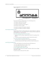
CHAPTER 6: Grounding and Powering the Gateway
40
Powering On the Gateway
Copyright © 2010, Juniper Networks, Inc.
2.
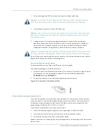
Attach an electrostatic discharge (ESD) grounding strap to your bare wrist and connect the
strap to one of the ESD points on the chassis. For more information about ESD, see
“Preventing Electrostatic Discharge Damage” on page 83.
3.
Remove the screws from the terminal studs.
4.
Secure each power cable lug to the terminal studs.
a.
Attach the negative wire lug to the negative (–) terminal stud.
b.
Attach the positive wire lug to the positive (+) terminal stud.
5.
Verify that the power cabling is correct, that the cables are not touching or blocking access to
the gateway and do not drape where people could trip on them.
6.
Repeat Steps 1 through 4 for connecting the other power supply.
7.
Connect the power cables to the power source.
Powering On the Gateway
To power on the gateway:
1.
Verify that an external management device is connected to the console port on the gateway.
For more information about connecting the console terminal, see “Connecting to a Console
2.
Turn on the power of the external management device.
3.
Verify that the power supply is fully inserted in the chassis.
4.
Verify that the source power cord is securely inserted into the appliance inlet.
5.
Switch on the customer site circuit breakers to provide voltage to the power supply.
When the gateway is powered on successfully and diagnostic tests are complete, the system
LED is lit green, indicating that the gateway and power supplies are functioning normally. See
6.
Monitor the startup process on the external management device to verify that the system has
booted properly.
Powering Off the Gateway
To power off the gateway:
1.
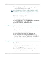
Issue the
request system reboot
command on the external management device connected
to the gateway to temporarily suspend the system operation. Use the
request system reboot
command to clear all committed and uncommitted commands.
cli@BX7000#
request system reboot
Reboot the system ? (yes or no): yes
Save current configuration for next reboot? (yes or no):
A confirmation message is displayed. You can either save the configurations or discard the
configuration.
Caution:
You must ensure that power connections maintain the proper polarity. The power
source cables might be labeled (
+
) and (
–
) to indicate their polarity. There is no standard color
coding for DC power cables. The color coding used by the external DC power source at your site
determines the color coding for the leads on the power cables that attach to the terminal studs
on each power supply.
Summary of Contents for BX7000
Page 10: ... x Copyright 2010 Juniper Networks Inc ...
Page 12: ... xii Copyright 2010 Juniper Networks Inc ...
Page 18: ...About This Guide xviii Requesting Support Copyright 2010 Juniper Networks Inc ...
Page 20: ... 2 Copyright 2010 Juniper Networks Inc ...
Page 66: ... 48 Copyright 2010 Juniper Networks Inc ...
Page 90: ... 72 Copyright 2010 Juniper Networks Inc ...
Page 122: ... 104 Hardware Compliance Copyright 2010 Juniper Networks Inc ...
Page 131: ...Copyright 2010 Juniper Networks Inc 113 Appendix E Declaration of Conformity ...
Page 132: ... 114 Copyright 2010 Juniper Networks Inc ...
Page 133: ...Copyright 2011 Juniper Networks Inc 115 PART 4 Index z Index on page 117 ...

