:
76
Power Guidelines, Requirements, and Specifications
Copyright © 2010, Juniper Networks, Inc.
Power Guidelines, Requirements, and Specifications
z
Site Electrical Wiring Guidelines on page 76
z
Chassis Grounding Specifications on page 76
z
AC Power Specifications on page 77
z
AC Power Cord Specifications on page 77
z
DC Power Specifications on page 78
z
DC Power Cable Specifications on page 78
Site Electrical Wiring Guidelines
When planning the electrical wiring at your site, consider the factors discussed in the following
sections:
Distance Limitations for Signaling
Improperly installed wires can emit radio interference. In addition, the potential for damage from
lightning strikes increases if wires exceed recommended distances or if wires pass between
buildings. The electromagnetic pulse (EMP) caused by lightning can damage unshielded
conductors and destroy electronic devices. If your site has previously experienced such problems,
you might want to consult experts in electrical surge suppression and shielding.
Radio Frequency Interference
You can reduce or eliminate the emission of radio frequency interference (RFI) from your site wiring
by using twisted-pair cable with a good distribution of grounding conductors. If you must exceed
the recommended distances, use a high-quality twisted-pair cable with one ground conductor for
each data signal when applicable.
Electromagnetic Compatibility
If your site is susceptible to problems with electromagnetic compatibility (EMC), particularly from
lightning or radio transmitters, you might want to seek expert advice. Strong sources of
electromagnetic interference (EMI) can destroy the signal drivers and receivers in the gateway and
conduct power surges over the lines into the equipment, resulting in an electrical hazard. It is
particularly important to provide a properly grounded and shielded environment and to use
electrical surge-suppression devices.
Chassis Grounding Specifications
To meet safety and electromagnetic interference (EMI) requirements and to ensure proper
operation, the gateway must be adequately grounded before power is connected. For grounding
the gateway, use a 14-AWG to 10-AWG wire whose length depends on the location where the
gateway will be mounted. Two grounding studs are provided on the right side of the front panel for
connecting the gateway to earth ground. One grounding screw is provided on the left side in the
rear of the gateway for connecting the gateway to the earth ground when it is mounted on the wall.
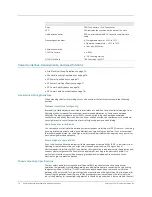
Ports
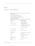
2 BNC connectors, 1 RJ-45 connector
LED
LED indicates the synchronization state of the clock
Cable and connector
BNC co-axial cable with BNC connector and interface
cable
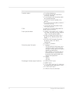
Operating environment
z
Storage temperature: –40°C to 70°C
z
Operating temperature: –40°C to 70°C
z
Humidity: 95% max.
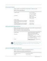
Power consumption
TCXO Clock card
OCXO Clock Card
z
6.82 W
z
10.2 W during start up
7.89 W ambient @ 25°C
Advanced Clocking Module
Description
Summary of Contents for BX7000
Page 10: ... x Copyright 2010 Juniper Networks Inc ...
Page 12: ... xii Copyright 2010 Juniper Networks Inc ...
Page 18: ...About This Guide xviii Requesting Support Copyright 2010 Juniper Networks Inc ...
Page 20: ... 2 Copyright 2010 Juniper Networks Inc ...
Page 66: ... 48 Copyright 2010 Juniper Networks Inc ...
Page 90: ... 72 Copyright 2010 Juniper Networks Inc ...
Page 122: ... 104 Hardware Compliance Copyright 2010 Juniper Networks Inc ...
Page 131: ...Copyright 2010 Juniper Networks Inc 113 Appendix E Declaration of Conformity ...
Page 132: ... 114 Copyright 2010 Juniper Networks Inc ...
Page 133: ...Copyright 2011 Juniper Networks Inc 115 PART 4 Index z Index on page 117 ...

