Connect the Timing Port
The
CLK
port on either of the interface modules is for an external network clock
reference interface. Only one clock interface is needed for the device:
■
The serial interface module has an HD-26
CLK
port (see Figure 3 on page 10).
■
The T1/E1 interface module has an RJ-45
CLK
port (see Figure 4 on page 11).
To connect the clock source input ports:
1.
Attach the appropriate connector to the
CLK
port.
2.
Attach the opposite end of the network timing cable to your network's clock
source A.
Connect the Serial Interface Module
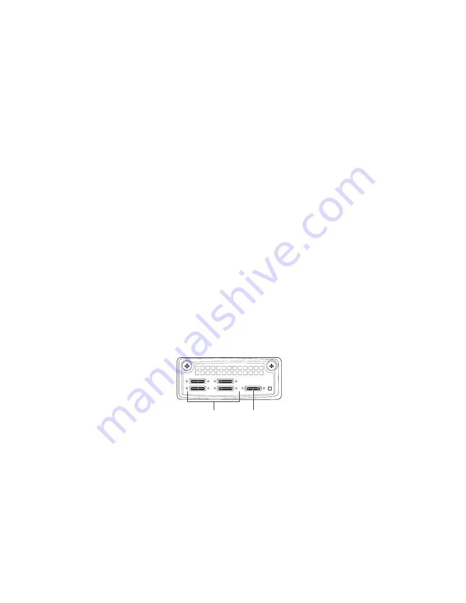
The CTP150 platform serial interface module provides four HD-26 ports (see Figure
3 on page 10). To install the cable in a port:
1.
Ground yourself by using an antistatic wrist strap or other device, and connect
it to an ESD grounding jack, or to some other grounding device.
2.
Remove the dust cover that protects the cable connectors.
3.
Slide the cable as far as you can into the module until it clicks into place.
4.
Gently pull the cable to confirm that it is inserted correctly.
Figure 3: CTP150 Platform Serial Interface Module
CLK
1
0
3
2
STATUS
g004483
HD-26 26-pin
connectors
Clock
connector
Connect the T1/E1 Interface Module
The CTP150 platform T1/E1 interface module provides four RJ-45 connector ports
(see Figure 4 on page 11). To install the cable in a port:
1.
Ground yourself by using an antistatic wrist strap or other device, and connect
it to an ESD grounding jack, or to some other grounding device.
2.
Remove the dust cover that protects the cable connectors.
3.
Slide the cable as far as you can into the module until it clicks into place.
4.
Gently pull the cable to confirm that it is inserted correctly.
10
■
Step 4: Connect Cables
CTP150 Platform Quick Start Guide


