WARNING:
Be sure circuit breakers for the power source are in the OFF position
before attaching power cables.
WARNING:
Remove jewelry (including rings, necklaces, and watches) before working
on equipment that is connected to power lines. Metal objects heat up when connected
to power and ground and can cause serious burns or become welded to the terminals.
WARNING:
Do not insert any metal object, such as a screwdriver, into an open slot
or the midplane. Doing so can cause electric shock and serious burns.
WARNING:
Never attempt to repair parts of modules yourself. Only trained customer
service personnel are authorized to service parts. Call Juniper Networks Customer
Service to make arrangements to return defective modules for repair.
Install an Interface Module
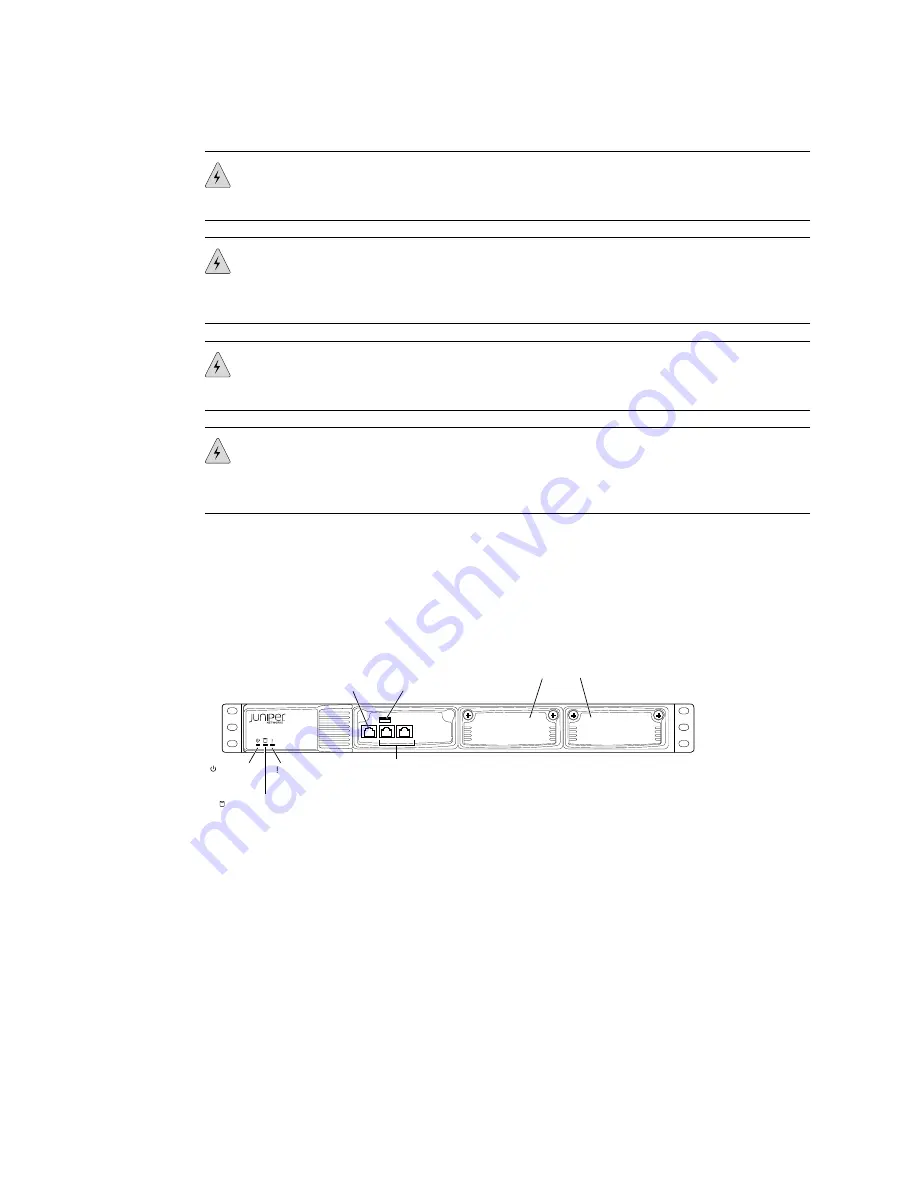
The CTP150 platform has two possible interface modules, the serial or T1/E1 interface
module, that fit into the slots on the right side of the chassis (see Figure 1 on page 7).
Figure 1: Interface Module Locations in the CTP150 Chassis
CTP150
g004480
CONSOLE ETH1
ETH0
Power
LED
Hardware
LED
Serial
Console port
Traffic
interfaces:
Two copper Ethernet ports
(10/100/1000 Mbps)
USB
port
Flash disk LED
Interface module slots
To install an interface module:
1.
Ground yourself by using an antistatic wrist strap or other device, and connect
it to one of the ESD grounding jacks, or to some other grounding device.
2.
Choose the slot where you want to insert the module.
3.
With a Phillips screwdriver, loosen the screws that secure the blank filler panel
covering the empty chassis slot, if present, and remove the filler panel.
4.
Remove the module from its antistatic bag, being careful not to touch module
components, pins, leads, or solder connections.
5.
Verify that the ejectors are in the open position (facing outward).
Step 3: Install Modules and Other Components
■
7
Step 3: Install Modules and Other Components


