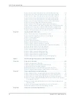
Figure 59: Mixed Mode VCF with a EX4300 Switch . . . . . . . . . . . . . . . . . . . . . . . 189
Figure 60: QFX3500 Using the 40G Ports as the VCPs . . . . . . . . . . . . . . . . . . . . . 191
Figure 61: QFX3500 Using the 10G Ports as the VCPs . . . . . . . . . . . . . . . . . . . . . 192
Figure 62: QFX3600 Using the 40G Ports as the VCPs . . . . . . . . . . . . . . . . . . . . 193
Figure 63: QFX3500 and QFX3600 Mixed Using the 40G Ports as the VCPs . . . 193
Figure 64: QFX3500 and QFX3600 Mixed Using Both 40G Ports and 10G Ports
as the VCPs . . . . . . . . . . . . . . . . . . . . . . . . . . . . . . . . . . . . . . . . . . . . . . . . . . . 194
Figure 65: QFX5100 Master Connecting QFX3600 and QFX3500 Using 40G
Ports as VCPs . . . . . . . . . . . . . . . . . . . . . . . . . . . . . . . . . . . . . . . . . . . . . . . . . 194
Chapter 14
Performing Initial Configuration . . . . . . . . . . . . . . . . . . . . . . . . . . . . . . . . . . . . 197
Figure 66: LCD Panel in an EX3200, EX4200, EX4500, EX4550, or EX8200
Switch . . . . . . . . . . . . . . . . . . . . . . . . . . . . . . . . . . . . . . . . . . . . . . . . . . . . . . . 209
Figure 67: LCD Panel in an EX4300 Switch . . . . . . . . . . . . . . . . . . . . . . . . . . . . . 209
Part 4
Installing, Maintaining, and Replacing Components
Chapter 15
Replacing Cooling System Component . . . . . . . . . . . . . . . . . . . . . . . . . . . . . . 217
Figure 68: Installing a Fan Module in a 24-Port EX4300 Switch . . . . . . . . . . . . . 218
Figure 69: Removing a Fan Module from an EX4300 Switch . . . . . . . . . . . . . . . . 219
Chapter 16
Replacing Power Supply . . . . . . . . . . . . . . . . . . . . . . . . . . . . . . . . . . . . . . . . . . . 221
Figure 70: Installing an AC Power Supply in an EX4300 Switch . . . . . . . . . . . . . . 222
Figure 71: Removing an AC Power Supply from an EX4300 Switch . . . . . . . . . . . 224
Figure 72: Installing a DC Power Supply in an EX4300 Switch . . . . . . . . . . . . . . . 226
Figure 73: Removing a DC Power Supply from an EX4300 Switch . . . . . . . . . . . . 227
Chapter 17
Replacing Uplink Module . . . . . . . . . . . . . . . . . . . . . . . . . . . . . . . . . . . . . . . . . 229
Figure 74: Installing a 4-Port SFP+ Uplink Module in a 24-Port or 48-Port EX4300
Switch . . . . . . . . . . . . . . . . . . . . . . . . . . . . . . . . . . . . . . . . . . . . . . . . . . . . . . . 230
Figure 75: Installing a 2-Port QSFP+ Uplink Module in a 32-Port EX4300
Switch . . . . . . . . . . . . . . . . . . . . . . . . . . . . . . . . . . . . . . . . . . . . . . . . . . . . . . . 230
Figure 76: Installing an 8-Port SFP+ Uplink Module in a 32-Port EX4300
Switch . . . . . . . . . . . . . . . . . . . . . . . . . . . . . . . . . . . . . . . . . . . . . . . . . . . . . . . . 231
Figure 77: Removing a 4-Port SFP+ Uplink Module from a 24-Port or 48-Port
EX4300 Switch . . . . . . . . . . . . . . . . . . . . . . . . . . . . . . . . . . . . . . . . . . . . . . . . 232
Figure 78: Removing a 2-Port QSFP+ Uplink Module from a 32-Port EX4300
Switch . . . . . . . . . . . . . . . . . . . . . . . . . . . . . . . . . . . . . . . . . . . . . . . . . . . . . . . 232
Figure 79: Removing an 8-Port SFP+ Uplink Module from a 32-Port EX4300
Switch . . . . . . . . . . . . . . . . . . . . . . . . . . . . . . . . . . . . . . . . . . . . . . . . . . . . . . . 233
Chapter 18
Replacing Transceiver . . . . . . . . . . . . . . . . . . . . . . . . . . . . . . . . . . . . . . . . . . . . 235
Figure 80: Installing a Transceiver in an EX Series Switch . . . . . . . . . . . . . . . . . . 237
Figure 81: Removing a Transceiver from a Switch . . . . . . . . . . . . . . . . . . . . . . . . . 239
Chapter 19
Maintaining and Replacing Fiber-Optic Cable . . . . . . . . . . . . . . . . . . . . . . . . 241
Figure 82: Connecting a Fiber-Optic Cable to an Optical Transceiver Installed in
a Switch . . . . . . . . . . . . . . . . . . . . . . . . . . . . . . . . . . . . . . . . . . . . . . . . . . . . . . 242
Chapter 20
Contacting Customer Support and Returning the Chassis or
Components . . . . . . . . . . . . . . . . . . . . . . . . . . . . . . . . . . . . . . . . . . . . . . . . . . . . 245
xi
Copyright © 2015, Juniper Networks, Inc.
List of Figures
Summary of Contents for EX4300
Page 1: ...EX4300 Switch Hardware Guide Modified 2015 06 29 Copyright 2015 Juniper Networks Inc ...
Page 16: ...Copyright 2015 Juniper Networks Inc xvi EX4300 Switch Hardware Guide ...
Page 22: ...Copyright 2015 Juniper Networks Inc xxii EX4300 Switch Hardware Guide ...
Page 24: ...Copyright 2015 Juniper Networks Inc 2 EX4300 Switch Hardware Guide ...
Page 102: ...Copyright 2015 Juniper Networks Inc 80 EX4300 Switch Hardware Guide ...
Page 104: ...Copyright 2015 Juniper Networks Inc 82 EX4300 Switch Hardware Guide ...
Page 128: ...Copyright 2015 Juniper Networks Inc 106 EX4300 Switch Hardware Guide ...
Page 172: ...Copyright 2015 Juniper Networks Inc 150 EX4300 Switch Hardware Guide ...
Page 176: ...Copyright 2015 Juniper Networks Inc 154 EX4300 Switch Hardware Guide ...
Page 218: ...Copyright 2015 Juniper Networks Inc 196 EX4300 Switch Hardware Guide ...
Page 236: ...Copyright 2015 Juniper Networks Inc 214 EX4300 Switch Hardware Guide ...
Page 238: ...Copyright 2015 Juniper Networks Inc 216 EX4300 Switch Hardware Guide ...
Page 250: ...Copyright 2015 Juniper Networks Inc 228 EX4300 Switch Hardware Guide ...
Page 256: ...Copyright 2015 Juniper Networks Inc 234 EX4300 Switch Hardware Guide ...
Page 278: ...Copyright 2015 Juniper Networks Inc 256 EX4300 Switch Hardware Guide ...
Page 286: ...Copyright 2015 Juniper Networks Inc 264 EX4300 Switch Hardware Guide ...
Page 292: ...Copyright 2015 Juniper Networks Inc 270 EX4300 Switch Hardware Guide ...
Page 306: ...Copyright 2015 Juniper Networks Inc 284 EX4300 Switch Hardware Guide ...
Page 312: ...Copyright 2015 Juniper Networks Inc 290 EX4300 Switch Hardware Guide ...
Page 336: ...Copyright 2015 Juniper Networks Inc 314 EX4300 Switch Hardware Guide ...


