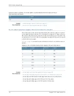
Table 76: Cable Specifications for Switch-to-Management-Device Connections
Additional
Information
Switch
Receptacle
Maximum Length
Cable/Wire
Supplied
Cable
Specification
Ports on EX4300
Switches
“Connecting a
Switch to a
Management
Console” on
page 183
RJ-45
7 ft (2.13 m)
One 7-ft (2.13-m)
length with
RJ-45/DB-9
connectors
CAT5e UTP
(unshielded
twisted pair) cable
RJ-45 Console
(
CON2
) port
“Connecting a
Switch to a
Network for
Out-of-Band
Management” on
page 181
–
–
No
–
Management
(
MGMT
) Ethernet
port
(10/100/1000)
“Connecting an
EX4300 Switch to
a Management
Console Using the
Mini-USB Type-B
Console Port” on
page 185
–
–
No
–
Mini-USB Type-B
Console (
CON1
)
port
Related
Documentation
Management Port Connector Pinout Information for an EX4300 Switch on page 142
•
•
Mini-USB Port Specifications for an EX4300 Switch on page 140
•
Console Port Connector Pinout Information for an EX Series Switch on page 139
•
EX4300 Switches Hardware Overview on page 3
Understanding EX Series Switches Fiber-Optic Cable Signal Loss, Attenuation, and
Dispersion
To determine the power budget and power margin needed for fiber-optic connections,
you need to understand how signal loss, attenuation, and dispersion affect transmission.
EX Series Switches use various types of network cable, including multimode and
single-mode fiber-optic cable.
•
Signal Loss in Multimode and Single-Mode Fiber-Optic Cable on page 137
•
Attenuation and Dispersion in Fiber-Optic Cable on page 138
Signal Loss in Multimode and Single-Mode Fiber-Optic Cable
Multimode fiber is large enough in diameter to allow rays of light to reflect internally
(bounce off the walls of the fiber). Interfaces with multimode optics typically use LEDs
as light sources. However, LEDs are not coherent light sources. They spray varying
wavelengths of light into the multimode fiber, which reflects the light at different angles.
Light rays travel in jagged lines through a multimode fiber, causing signal dispersion.
When light traveling in the fiber core radiates into the fiber cladding (layers of lower
refractive index material in close contact with a core material of higher refractive index),
137
Copyright © 2015, Juniper Networks, Inc.
Chapter 8: Transceiver and Cable Specifications
Summary of Contents for EX4300
Page 1: ...EX4300 Switch Hardware Guide Modified 2015 06 29 Copyright 2015 Juniper Networks Inc ...
Page 16: ...Copyright 2015 Juniper Networks Inc xvi EX4300 Switch Hardware Guide ...
Page 22: ...Copyright 2015 Juniper Networks Inc xxii EX4300 Switch Hardware Guide ...
Page 24: ...Copyright 2015 Juniper Networks Inc 2 EX4300 Switch Hardware Guide ...
Page 102: ...Copyright 2015 Juniper Networks Inc 80 EX4300 Switch Hardware Guide ...
Page 104: ...Copyright 2015 Juniper Networks Inc 82 EX4300 Switch Hardware Guide ...
Page 128: ...Copyright 2015 Juniper Networks Inc 106 EX4300 Switch Hardware Guide ...
Page 172: ...Copyright 2015 Juniper Networks Inc 150 EX4300 Switch Hardware Guide ...
Page 176: ...Copyright 2015 Juniper Networks Inc 154 EX4300 Switch Hardware Guide ...
Page 218: ...Copyright 2015 Juniper Networks Inc 196 EX4300 Switch Hardware Guide ...
Page 236: ...Copyright 2015 Juniper Networks Inc 214 EX4300 Switch Hardware Guide ...
Page 238: ...Copyright 2015 Juniper Networks Inc 216 EX4300 Switch Hardware Guide ...
Page 250: ...Copyright 2015 Juniper Networks Inc 228 EX4300 Switch Hardware Guide ...
Page 256: ...Copyright 2015 Juniper Networks Inc 234 EX4300 Switch Hardware Guide ...
Page 278: ...Copyright 2015 Juniper Networks Inc 256 EX4300 Switch Hardware Guide ...
Page 286: ...Copyright 2015 Juniper Networks Inc 264 EX4300 Switch Hardware Guide ...
Page 292: ...Copyright 2015 Juniper Networks Inc 270 EX4300 Switch Hardware Guide ...
Page 306: ...Copyright 2015 Juniper Networks Inc 284 EX4300 Switch Hardware Guide ...
Page 312: ...Copyright 2015 Juniper Networks Inc 290 EX4300 Switch Hardware Guide ...
Page 336: ...Copyright 2015 Juniper Networks Inc 314 EX4300 Switch Hardware Guide ...


