Depending on the power supplies installed in the switch, you can determine the system
power budget.
•
If one power supply is installed in the switch:
System power budget = Output wattage of the installed power supply (PSU(W))
•
If two power supplies are installed in the switch:
System power budget = (Sum of the output wattage of the two power supplies) –
(10% of the output wattage of the installed power supply)
System power budget = PSU
0
(W) + PSU
1
(W) – (0.10 x (PSU(W))
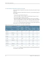
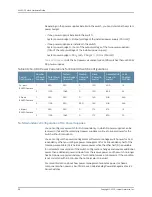
Table 38 on page 58
lists the
N
+0 power calculation for EX4300 switches that use 550 W
DC power supplies.
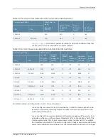
Table 38: N+0 DC Power Calculations for EX4300 Switch Configurations
Ports
Enabled
for PoE+
Available PoE
Power (in
watts)
Base
Power (in
watts)
Backup
Power (in
watts)
System
Power Budget
(in watts)
Total Power
(in watts)
Number
of Power
Supplies
Switch
Configuration
13
400
150
0
550
550
1
24-port
EX4300 switch
24
895
150
0
1045
1100
2
N/A
N/A
149
0
550
550
1
32-port
EX4300 switch
N/A
N/A
160
550
550
1100
2
12
375
175
0
550
550
1
48-port
EX4300 switch
29
870
175
0
1045
1100
2
N+N Redundancy Configuration of DC Power Supplies
You can configure your switch for
N
+
N
redundancy, in which
N
power supplies can be
removed or fail and the remaining
N
power supplies continue to supply power for the
switch without interruption.
You can configure the power management software to manage switch power for
N
+
N
redundancy. When you configure power management for
N
+
N
redundancy, half of the
total power available (
N
) is held as reserve power while the other half (
N
) is available
for immediate consumption. If the switch configuration changes and requires additional
power, then additional power is drawn from the reserve power, and the switch no longer
has
N
+
N
power supply redundancy. This condition raises a minor alarm. If the condition
is not corrected within 5 minutes, then a major alarm is issued.
For more information about how power management allocates power to chassis
components when power is insufficient, see
Understanding Power Management on EX
Series Switches
.
Copyright © 2015, Juniper Networks, Inc.
58
EX4300 Switch Hardware Guide
Summary of Contents for EX4300
Page 1: ...EX4300 Switch Hardware Guide Modified 2015 06 29 Copyright 2015 Juniper Networks Inc ...
Page 16: ...Copyright 2015 Juniper Networks Inc xvi EX4300 Switch Hardware Guide ...
Page 22: ...Copyright 2015 Juniper Networks Inc xxii EX4300 Switch Hardware Guide ...
Page 24: ...Copyright 2015 Juniper Networks Inc 2 EX4300 Switch Hardware Guide ...
Page 102: ...Copyright 2015 Juniper Networks Inc 80 EX4300 Switch Hardware Guide ...
Page 104: ...Copyright 2015 Juniper Networks Inc 82 EX4300 Switch Hardware Guide ...
Page 128: ...Copyright 2015 Juniper Networks Inc 106 EX4300 Switch Hardware Guide ...
Page 172: ...Copyright 2015 Juniper Networks Inc 150 EX4300 Switch Hardware Guide ...
Page 176: ...Copyright 2015 Juniper Networks Inc 154 EX4300 Switch Hardware Guide ...
Page 218: ...Copyright 2015 Juniper Networks Inc 196 EX4300 Switch Hardware Guide ...
Page 236: ...Copyright 2015 Juniper Networks Inc 214 EX4300 Switch Hardware Guide ...
Page 238: ...Copyright 2015 Juniper Networks Inc 216 EX4300 Switch Hardware Guide ...
Page 250: ...Copyright 2015 Juniper Networks Inc 228 EX4300 Switch Hardware Guide ...
Page 256: ...Copyright 2015 Juniper Networks Inc 234 EX4300 Switch Hardware Guide ...
Page 278: ...Copyright 2015 Juniper Networks Inc 256 EX4300 Switch Hardware Guide ...
Page 286: ...Copyright 2015 Juniper Networks Inc 264 EX4300 Switch Hardware Guide ...
Page 292: ...Copyright 2015 Juniper Networks Inc 270 EX4300 Switch Hardware Guide ...
Page 306: ...Copyright 2015 Juniper Networks Inc 284 EX4300 Switch Hardware Guide ...
Page 312: ...Copyright 2015 Juniper Networks Inc 290 EX4300 Switch Hardware Guide ...
Page 336: ...Copyright 2015 Juniper Networks Inc 314 EX4300 Switch Hardware Guide ...

