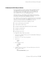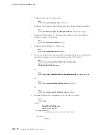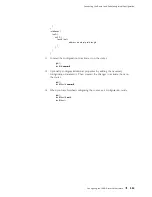
M160 Internet Router Hardware Guide
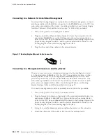
Connecting to a Network for Out-of-Band Management
To connect the Routing Engine to a network for out-of-band management, connect
an Ethernet cable with RJ-45/RJ-45 connectors to the
ETHERNET
port on the CIP. One
such cable is provided with the router. For cable specifications, see Routing Engine
Interface Cable and Wire Specifications on page 74. Follow this procedure:
1.
Turn off the power to the management device.
2.
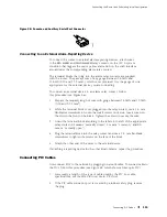
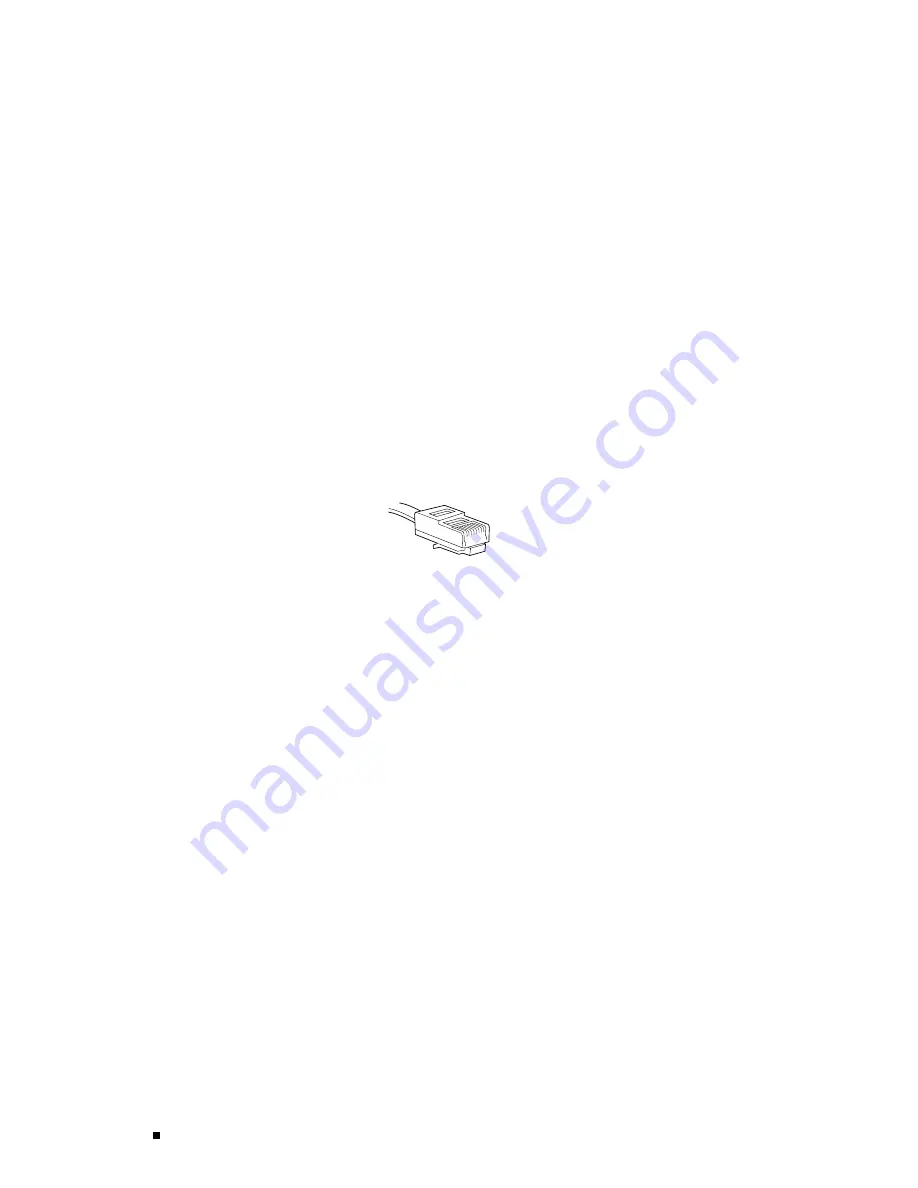
Plug one end of the Ethernet cable (Figure 57 shows the connector) into the
appropriate
ETHERNET
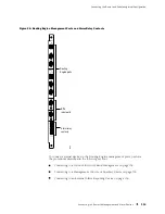
port on the CIP. Figure 56 shows the external device
ports on the CIP. The ports labeled
HOST 0
connect to the Routing Engine in the
upper Routing Engine slot (
RE 0
), and the ports labeled
HOST 1
connect to the
Routing Engine in the lower Routing Engine slot (
RE 1
).
3.
Plug the other end of the cable into the network device.
Figure 57: Routing Engine Ethernet Cable Connector
g001063
Connecting to a Management Console or Auxiliary Device
To use a system console to configure and manage the Routing Engine, connect
it to the appropriate
CONSOLE
port on the CIP. To use a laptop, modem, or other
auxiliary device, connect it to the appropriate
AUXILIARY
port on the CIP. Both
ports accept an RS-232 (EIA-232) serial cable with DB-9/DB-9 connectors. One
such cable is provided with the router. If you want to connect a device to both
ports, you must supply another cable. For cable specifications, see Routing
Engine Interface Cable and Wire Specifications on page 74.
To connect a management console or auxiliary device, follow this procedure:
1.
Turn off the power to the console or auxiliary device.
2.
Plug the female end (shown in Figure 58) of the provided serial cable into the
appropriate
CONSOLE
or
AUXILIARY
port. Figure 56 shows the external device
ports on the CIP. The ports labeled
HOST 0
connect to the Routing Engine in the
upper Routing Engine slot (
RE 0
), and the ports labeled
HOST 1
connect to the
Routing Engine in the lower Routing Engine slot (
RE 1
).
3.
Using a 2.5 mm flat-blade screwdriver, tighten the screws on the connector.
4.
Attach the other end of the cable to the console or auxiliary device.
114
Connecting the Router to Management and Alarm Devices
Summary of Contents for Internet Router M160
Page 12: ...M160 Internet Router Hardware Guide xii Table of Contents ...
Page 16: ...M160 Internet Router Hardware Guide xvi List of Figures ...
Page 18: ...M160 Internet Router Hardware Guide xviii List of Tables ...
Page 24: ...M160 Internet Router Hardware Guide xxiv Requesting Support ...
Page 26: ...2 Product Overview ...
Page 30: ...M160 Internet Router Hardware Guide 6 Safety Requirements Warnings and Guidelines ...
Page 66: ...M160 Internet Router Hardware Guide 42 Cable Management System ...
Page 80: ...M160 Internet Router Hardware Guide 56 Routing Engine Architecture ...
Page 82: ...58 Initial Installation ...
Page 104: ...M160 Internet Router Hardware Guide 80 Unpacking the Router ...
Page 148: ...M160 Internet Router Hardware Guide 124 Configuring the JUNOS Internet Software ...
Page 150: ...126 Hardware Maintenance Replacement and Troubleshooting Procedures ...
Page 242: ...M160 Internet Router Hardware Guide 218 Troubleshooting the Power System ...
Page 244: ...220 Appendixes ...
Page 292: ...M160 Internet Router Hardware Guide 268 Packing Components for Shipment ...
Page 301: ...Part 5 Index Index 277 ...
Page 302: ...278 Index ...


